Nice work, Lukas. It looks sturdy, too.
A larger transformer would help the bass somewhat, but we still need subs unless the ESL panel size is large.
How large is your panel?
Sound is not that bad , even with poor transformer , and it has bass, though i feel that a sub is needed.
A larger transformer would help the bass somewhat, but we still need subs unless the ESL panel size is large.
How large is your panel?
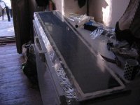
Hi, dstockwell. I took some time to design the frame for the ESL panels. I tend to overengineer things, so progress has been slow. I'll have more pictures of the finished frame soon.
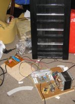
Here's a work in progress picture of the frame with the ESL panel and electronics temporarily in place.
A closer look at the electronics.
My wife and I got a new dog that's been keeping us busy. She's a German Shepherd named Kola. In between eating and running around the house, she takes a break to sleep.
I'm trying a new image hosting service. Let me know what you think about the pictures. Click the pics to see them full size.
Here's a work in progress picture of the frame with the ESL panel and electronics temporarily in place.
An externally hosted image should be here but it was not working when we last tested it.
A closer look at the electronics.
An externally hosted image should be here but it was not working when we last tested it.
My wife and I got a new dog that's been keeping us busy. She's a German Shepherd named Kola. In between eating and running around the house, she takes a break to sleep.
An externally hosted image should be here but it was not working when we last tested it.
I'm trying a new image hosting service. Let me know what you think about the pictures. Click the pics to see them full size.
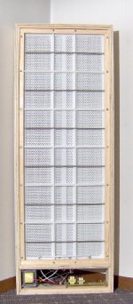
The enclosure and wiring are almost done. The outer plywood skin measures 43-1/4" x 15-3/4" x 3-3/4". Inside of that, the inner front and back frames hold the ESL panel in place, attached to each other with eighteen 8-32 screws.
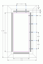
The ESL panel is held together with four 4-40 nylon screws, one in each corner, just to hold it together until the panel gets mounted to the frames. The edge of the panel gets squeezed between the frames with a thin, self adhesive foam from the craft section at Walmart between the frames and the panel. I still have to pick out a foam color. 😀
I've tried to make the ESL panel as stiff as possible with 1/4" thick acrylic vertical ribs. I needed a way to hold the inner part of the ESL panel together and I didn't want to glue the two halves of the panel together. The small grey horizontal strips in the picture are 5/32" diameter round steel bars, six in each frame, one behind the other. They're deflecting about 1/8" in the middle, squeezing the two halves of the ESL panel together when the frames are tightened.
Attachments
The build is still moving along. There's a lot of small details to take care of before final assembly. I've made another order to Mouser to get the parts I forgot on the first order from them. They should be here in four days. I'm bidding on some walnut veneer from a seller on Ebay to cover the enclosures. The enclosures have been sealed on the inside with clear polyurethane. I still need to paint the steel tension rods.
Here's a drawing of the stretcher I'm building. The outer part of it is glued and the whole stretcher should be done in a couple of days. It's built with 2" x 4" lumber salvaged from pallets. The diaphragm is tensioned by tightening nuts on the running thread on two sides. I'm not sure how well it will work with pull on only two sides, rather than four. The dark bars in the inner four pieces represent slots that will have 7/64" plastic spline pressed in to hold the diaphragm n place while stretching. It's the same spline used to hold the screen in screen doors.
Here's a drawing of the stretcher I'm building. The outer part of it is glued and the whole stretcher should be done in a couple of days. It's built with 2" x 4" lumber salvaged from pallets. The diaphragm is tensioned by tightening nuts on the running thread on two sides. I'm not sure how well it will work with pull on only two sides, rather than four. The dark bars in the inner four pieces represent slots that will have 7/64" plastic spline pressed in to hold the diaphragm n place while stretching. It's the same spline used to hold the screen in screen doors.
Attachments
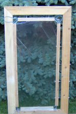
Here's a photo of the stretcher with the first piece of Hostaphan diaphragm installed. I learned some things that will need to be fixed on the next try. The first thing I noticed was how hard it was to get the diaphragm tensioned equally as I pushed the plastic spline into the grooves around the outside. It turned out OK, the multiple threaded rods let me skew the tension to get a nice flat film.
I tapped the diaphragm with a finger, tensioned some more, tapped again, tensioned again until it sounded like a drum head. It works!
Then it happened... A small rip revealed itself and that's why you see ripples in the picture. As I was inserting the spline earlier, the spline tool slipped and must have cut or weakened the diaphragm. No problem as this was a test run. One of our dogs put her foot through the diaphragm shortly after this picture was taken and I accidently put my elbow through it as I was bringing it back in the house. Gotta treat the Hostaphan a little better next time. 😀
I'm having trouble with the digital camera, it cuts off the bottom of pictures. The bottom of the frame is actually as wide as the rest of it.
Attachments
I think it will be difficult to get good results from such a diaphragm stretcher. There are a couple problems with it, and you can see evidence of them in the photo.
You have secured the film to the stretcher bars by trapping it between a spline and a groove in the bars. The problem with this is that it does not allow the film to stretch at the point of attachment to the stretcher bar. That means the majority of the stretching is occuring at the corners where the film is not so constrained.
If you stretched the diaphragm in one direction, say the y axis, with the edges of the film unattached to the bars that provide the x stretch, then the film would stretch in the y direction, no problem. Now if you attach the film to the x bars and try to stretch in the y direction, what will happen? It will wrinkle because you're not allowing the edges of the film to stretch in the y direction. Now restrict both x and y edges of the film and try to stretch it and what do you get? You will put very large tension on the unrestricted corners of the film while putting almost none at the center. Your film stretching will have to stop before the diaphragm splits, which will occur first at the corners since they are under the most tension.
High tension prevents the diaphragm from moving too far and hitting the stators. In the corners and at the edges of the speakers, the film can't hit the stators because it is supported by the insulators, so having high tension in the corners and at the edges is not so important. The center of the diaphragm is where you have to worry about hitting the stators, so that is where you really need the tension.
The ideal(?) situation would be to have uniform tension over the surface of the diaphragm. This can be achieved by using a circular stretcher, but it is usually not practical due to the width of the diaphragm film that is comercially available (works great for headphones and microphones). Since uniform tension is not practical, the next best thing is to get the tension at the center of the film up so that it will be less likely to contact the stators.
You can make a much simpler stretcher that will provide more uniform and much higher tension by simply stretching a bicycle tire tube around a table that is a little larger than the speaker. Lay the film out over the table and uninflated tube and attach the film to the inside/underside edge of the table using either tape or a spline and groove.
Inflating the tube will stretch the film very tight, with more uniform results than the x-y stretcher. As you inflate the tube you will notice that the film is able to slide/stretch over the tube (unlike the spline and groove in your design). You will also notice that the corners inflate less than the long dimensions of the driver. This means the tension in the central area of the diaphragm will be quite high, while the corners will be lower and less likely to split. The air in the tube can and will go wherever it needs to to make the tension approximately uniform. If the film is pulling tight at one location, it will restrict stretching of the tube and force the air to go where there is less tension, thus equalizing (approximately) the tension everywhere.
I have not tried to make a stretcher table for such a long, narrow driver, so you may run into some problems there, but for drivers that are a little closer to square, the pneumatic stretcher works great. I suggest you give it a try. It only takes an hour or so to make one. It shouldn't matter that the table is bigger than a tire tube. Tubes stretch a lot.
I_F
Stretcher
Hi,
as Forgot said, Your stretcher is not designed for very good results.
I used a quite similar stretcher to good results but with the following differences.
In the Y-direction (long) I divided the moveable parts into 2 to 3 sections, each section with two threaded rods with nuts to screw the diaphragm tight. I used 1 section on each of the X-sides. So there are 6 to 8 sections connected to the outer frame. The threaded rods of the Y-sides run in small slots, so the sections can move a bit when stretching in the Y-direction. While the outer frame has to be very strong the moveable parts can be made from coated MDF-board, 30mm wide. You can glue the diaphragm to it with double sided sticky tape. This way You can get very high tension in one or both directions. The sticky tape is easily removed after stretching. If You replace the straight X-sections by bowed ones You can even stretch the diaphragm for ML-type panels 😉
jauu
Calvin
I_F and Calvin, thanks for the input.
I did have a feeling something wasn't quite right with the stretcher. I may be able to equalize the stretch better by securing the y first and stretching it and then securing and stretching the x. The spline seems to pull the film too much when it is installed. I'll try tape to hold the film instead and see what happens.
I_F, I originally wanted to try the inner tube stretcher, but a 27" inner tube, the largest I could find seemed too small to fit around a jig for my panel that measures 14-3/4" x 37-1/16". The other difficulty I had with it conceptually was getting the width and height to stretch unequally. Since the y must stretch more than the x, do you think an inner tube would work as a rectangle? It seems to be a perfect solution as long as the jig is a circle.
Calvin, I could easily separate the stretcher into multiple sections and oval some of the clearance holes for the threaded rods.
I like both of your ideas. I'll try them this weekend and get back to you.
Hi,
It is possible to use tape to hold mylar. But you need to bend it over edges , otherwise it will not hold the tension.Also , a well-adhering tape is required. The cheap transparent packing scotch is not suitable here.
I think that you could also use wooden sticks with screws to press the mylar to frame. Also , you could glue some type of rubber on the stick,
so that mylar would not slip out.
Here is the idea that i used to strech mylar.I used slow-bond epoxy.
Note : the transparent tape shown in picture is not good - it does not bond well to wood.But there are many type of tapes that bond much better.
Attachments
BillH said:
I_F, I originally wanted to try the inner tube stretcher, but a 27" inner tube, the largest I could find seemed too small to fit around a jig for my panel that measures 14-3/4" x 37-1/16". The other difficulty I had with it conceptually was getting the width and height to stretch unequally. Since the y must stretch more than the x, do you think an inner tube would work as a rectangle? It seems to be a perfect solution as long as the jig is a circle.
If a single tube won't stretch to fit, you can use two tubes, one for the upper and one for the lower half of the driver. The middle section, where the two tubes are laying next to each other can be wrapped with duct tape to keep them from stretching and force the air out to where it needs to be.
--
| |
| | top half
--
--
| |
| | bottom half
--
The air in the tube(s) will take care of making the tension even. While inflating, if the tension on the film gets high on one axis, it will keep the tube from stretching that axis any further and addional air will go to stretching the other axis. With two tubes you'll need to match the inflation pressures, but that shouldn't be hard to do.
Let us know how you manage it...
I_F
Hi Folks,
why messing around with mechanical stretching ?
- Put mylar on an even surface
- Stretch it, so no major wrinkles are visible (it don't need to be uniform)
- Glue it on the spacer frame
- Heat it with a heat gun at about 150°C
- Each panel will be within +/- 10 Hz resonance
Thats it
capaciti
why messing around with mechanical stretching ?
- Put mylar on an even surface
- Stretch it, so no major wrinkles are visible (it don't need to be uniform)
- Glue it on the spacer frame
- Heat it with a heat gun at about 150°C
- Each panel will be within +/- 10 Hz resonance
Thats it
capaciti
Heat shrinking does not provide sufficient tension to keep the diaphragm stable with high bias voltage. You have to use a low bias voltage to prevent the diaphragm from flapping, so the speaker will be very insensitive.
I_F
I_F
Hi I forgot,
Thats true, but a mechanically stretched membrane will increase its compliance and reduce resonance over the time.
people wonder why a new mechanically streched membrane ist stable first and collapses months later.
My experience is that over years the stretched membrane "creeps". It stops exactly at the tension of a heat shrinked . When it stops depends on listening level and membrane excursion.
Capaciti
Capaciti,
While I mostly agree with your point, I have witnessed creep relaxation with heat shrunk membranes over time too, although perhaps at a lesser rate than with mechanically stretched membranes. These properties are probably material specific.
While I mostly agree with your point, I have witnessed creep relaxation with heat shrunk membranes over time too, although perhaps at a lesser rate than with mechanically stretched membranes. These properties are probably material specific.
Hi Brian,
the relaxation is less than 10 % for a heat shrinked and more than 50% for a mechanically stretched membrane.
Why does mylar creep ?
at manufacturing the polymer-chains of mylar are stretched and oriented to a certain level, in order to provide the best mechanical performance.
When you stretch mechanically, you give the polymer-chains another orientation and you further stretch the chains. All the chains are linked to each other at several connection points. Those points crack more and more by time and movement, enabling the polymer to expand further, thus lossing tension. The connections brake due to the tension overload of the stretched membrane.
When you heat shrink, you weaken the matrix of the ploymer-chains. Doing this the orientation and stretching of the manufacturing will be reversed and the membrane shrinks. It shrinks exactly to a size, where the internal stress of the polymer-chains is balanced with the increasing tension due to shrinking. By giving enough heat, you allow each chain to "find" ist best fit for orientation and internal stress. This is the only way to expect longterm stability. The heat shrinked membrane will slighty loose tension, since some interconnections of the chain are "damaged" by the heat. After some cycles (a few hours of listening) the damaged connections will brake. After this is finished, the membrane is in its final and stable condition.
Capaciti
So it should be possible to overtension and allow the film to relax to the correct Fo, but how long will it take?Capaciti writes: the relaxation is less than 10 % for a heat shrinked and more than 50% for a mechanically stretched membrane.
I searched the web for other's experience with the Hostapan film I'm using and found this page which says in part:
A new batch of Hostaphan RE-6 (6 micron, 795 mm in width) has arrived, a perfect material to use as diaphragm material. It is the German equivalent to Mylar C, a tenselized PET film that will heat shrink for about two percent, ideal to get a perfect tension for your membrane.
And from this page:
I do not recommend heat to shrink the mylar, at least in Hostaphan the film the author uses, as the elongation factor is quite low, and is not the same in both dimensions and most importantly the applied tension is not easily controllable. Heat, however may be useful in adjusting small differences in tension to enable the matching of the Fo of a particular panel. If the Fo of a particular panel is too low hot air from hair drier or heat gun can be used to increase tension slightly and bring the Fo up to the other value. The procedure must be carried out with care and the tension increased gradually until the desired Fo is reached.
I think the second method has merit. If heat shrinking two films without an equal starting tension, it could be hard to get them both shrunk to the same Fo. You'd also be able to apply more tension with heat later when they stretch.
- Status
- Not open for further replies.
- Home
- Loudspeakers
- Planars & Exotics
- The ESL Build Thread