Hi,
In fact , i have had problems with small transformer heating as well.
I think you should try the following :
Test if the trannie does not heat without a load;
Measure the iddle and loaded current of transformers;
Try to put two same secondary voltage trannies, i.e 5v and 5v.
Some small transformers (especially chinese types 🙂 )have a considerable idle current(i measured 30 mA for a few watt transformer), which may cause them to heat.
Regards,
Lukas.
Hi, Lukas.
You are right about the transformers. The only way I could use two transformers back to back was to use transformers with equal voltage secondaries. They ran cool, but any other combination of voltages caused heating in one or both of the transformers.
So I have no HV bias supplies. I'm going to have to start from the beginning and build some new ones. Rod Elliot's HV supply looks like the best one at the moment. All the parts are available at reasonable cost and I can use the 12.6V 15VA transformers I bought yesterday to power it. The schematic is in the middle of this page.
I'm going to design the printed circuit boards to include the X10 voltage multiplier and the 20Meg series resistor, similar to the first boards. I'll be able to reuse the 10nF SMD capacitors from the first board, but have to replace the diodes with fast recovery types.
You are right about the transformers. The only way I could use two transformers back to back was to use transformers with equal voltage secondaries. They ran cool, but any other combination of voltages caused heating in one or both of the transformers.
So I have no HV bias supplies.
I'm going to have to start from the beginning and build some new ones. Rod Elliot's HV supply looks like the best one at the moment. All the parts are available at reasonable cost and I can use the 12.6V 15VA transformers I bought yesterday to power it. The schematic is in the middle of this page. I'm going to design the printed circuit boards to include the X10 voltage multiplier and the 20Meg series resistor, similar to the first boards. I'll be able to reuse the 10nF SMD capacitors from the first board, but have to replace the diodes with fast recovery types.
Ah, success finally. I've got a prototype high voltage power supply working on the breadboard. I went back to Sheldon Stokes' original power supply (pdf file) and altered it a bit so I could modify my first power supply attempt and use new parts I have on hand.
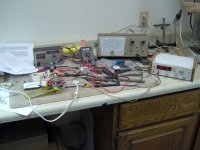
Here's a photo of the work in progress. It's hard to see 😉, but the power supply is on the bottom left.
Here's a photo of the work in progress. It's hard to see 😉, but the power supply is on the bottom left.
Attachments
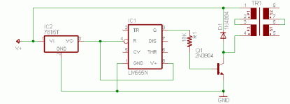
Here's the schematic. Instead of using two transformers directly connect to step up the voltage, there's a bridge rectifier and an LM555 chopper between them. The frequency of the chopper is set to the resonant frequency of the second transformer, 6630Hz.
I'm getting 410V RMS at the output of the second transformer and both transformers are running cool to the touch. The first 110V:12.6V transformer feeds a bridge rectifier and filter capacitors to give 19.1V DC when running. The circuit draws 42mA, well within the current limits of the first transformer and the LM555.
The LM555 section is a standard astable multivibrator. I'll replace R2 with a series connected 6.8K resistor and 5K trimpot when it gets built. The circuit detunes a bit and output voltage drops when a load is connected and I'll need to trim the oscillation frequency to keep the voltage up. The circuit that this is based on had an LM317 regulator before the LM555 that I left out. It was there to adjust output voltage, but I find that I can do that just by changing the oscillator frequency.
The transformer feeding the second transformer is wired for 10V:220V. I tried wiring it for 5V:220V, but only gained 10% more voltage for a 50% increase in current draw.
The only change I have to make to the current power supply boards is to break the connections between the two transformers. All the components between the transformers will be on a small perfboard. Now I need to build a pair of them. 🙂
Attachments
This seems very similar (actually pretty much identical) to the setup I'm using.
Well it was actually Sheldon's design, but I haven't seen him around here for a few years...
Here is a link with PCB layouts, schematics etc etc etc
http://www.quadesl.com/diy_esl1.html
-WES
Well it was actually Sheldon's design, but I haven't seen him around here for a few years...
Here is a link with PCB layouts, schematics etc etc etc
http://www.quadesl.com/diy_esl1.html
-WES
Hi, WES.
The power supply did end up to be Sheldon's v1.0 with some changes. I started with his v2.0, but it didn't work. I could use all of v2.0 and add the chopper circuit from v1.0.
Here's the schematic of the chopper. The changes to Sheldon's design are minor. I used a 7805 regulator I had on hand and lifted the ground with 3.3K resistors to get between 15 and 16 volts from the regulator. The chopper has a variable resistor to fine tune for maximum output voltage to the votage multiplier. The capacitor on pin 3 of the LM555 was changed from 10uF to .0047uF to raise the resonant frequency of the transformer/capacitor to get it out of audible range. With the original 10uF capacitor, I could hear the transformer oscillating.
Attachments

Hi Bill,
I am wondering about the LM555, as it feeds the 2nd transformer directly. Wouldn't it be better to implement a transistor ? I don't know if the LM555 will handle the current permanently.
Capaciti
I am wondering about the LM555, as it feeds the 2nd transformer directly. Wouldn't it be better to implement a transistor ? I don't know if the LM555 will handle the current permanently.
Capaciti
Hi,
LM555 has 200mA source or sink current , which should be enough.It is good to measure with AC ampere meter , probably right after the power supply transformer before rectifiers. Measuring current after LM555 will probably show wrong values , because the timer generates square wave.
By the way , BillH, why don't you use simple configuration of back-to back transformers , with the same voltage ? It is even possible to build a simple 220-220V transformer (or even 120:220) from two same trannies with separate windings. You just need to dissasemble both , and separate 220 and low voltage windings , and put two 220V.Then , assemble the trafo and immerse it in nitrocelulose lacquer for 5 minutes , dry out.Fast drying spray lacquer should work as well.This is quite fast , because the windings are usually not glued to each other , probably because manufacturer wants flexibility.
Regards,
Lukas.
Lukas writes: By the way , BillH, why don't you use simple configuration of back-to back transformers , with the same voltage ?
I tried it and it worked, but I'm looking for more voltage than it could give me. It's a very good way of getting 220V from 110V as long as the secondaries are of equal voltage.
Capaciti writes: I am wondering about the LM555, as it feeds the 2nd transformer directly. Wouldn't it be better to implement a transistor ?
The chopper operates at well under 200 ma so the 555 is safe. You have given me an idea, though. Adding the regulator dropped the output voltage from the transformer from 410V to 300V. I'd like to see if I can use the transistor as a level shifter, controlled by the 555, but fed from the unregulated and higher input voltage and maybe get a a few more volts out of it.
Here's a simplified schematic.
Attachments
Hi, all. The build is still alive!
I took some time off from posting to completely rebuild a pair of HV bias supplies. Rather than turn the thread into a long 'How to design and build a high voltage boost power supply', I'll try to keep it short.
First, some things I learned:
If the test meter doesn't show what is expected, check the meter.
My old Heathkit VTVM was having trouble reading AC with dirty switch contacts.
Digital VOMs don't like high voltage.
They break, luckily mine was cheap to replace.
If the test meter doesn't show what is expected, check the parts.
I fried a two mosfets and spent a few days trying to figure out what was wrong.
Keep a box of spare parts around even if your wife/roomate/signifigant other thinks it's crazy. 😉
One of the parts vendors I've used for years with no problems messed up an order. No problem, I took some capacitors from a junk TV board and got pinhead jumpers from an old ISA computer board.
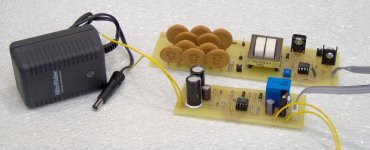
The picture shows one complete system. There's a 16.8VDC 300 ma wall transformer on the left. That feeds an Elliot Sound Products Project 38 'Signal Detecting Auto Power-On Unit'. It has only been changed to use a single speaker level input and added dropping resistors on the 9V relay that I had in the junkbox. The 'Power-On Unit' feeds unregulated DC to the next board, a DC chopper and voltage multiplier, when it detects speaker activity.
I took some time off from posting to completely rebuild a pair of HV bias supplies. Rather than turn the thread into a long 'How to design and build a high voltage boost power supply', I'll try to keep it short.
First, some things I learned:
If the test meter doesn't show what is expected, check the meter.
My old Heathkit VTVM was having trouble reading AC with dirty switch contacts.
Digital VOMs don't like high voltage.
They break, luckily mine was cheap to replace.
If the test meter doesn't show what is expected, check the parts.
I fried a two mosfets and spent a few days trying to figure out what was wrong.
Keep a box of spare parts around even if your wife/roomate/signifigant other thinks it's crazy. 😉
One of the parts vendors I've used for years with no problems messed up an order. No problem, I took some capacitors from a junk TV board and got pinhead jumpers from an old ISA computer board.
The picture shows one complete system. There's a 16.8VDC 300 ma wall transformer on the left. That feeds an Elliot Sound Products Project 38 'Signal Detecting Auto Power-On Unit'. It has only been changed to use a single speaker level input and added dropping resistors on the 9V relay that I had in the junkbox. The 'Power-On Unit' feeds unregulated DC to the next board, a DC chopper and voltage multiplier, when it detects speaker activity.
Attachments
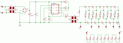
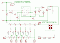
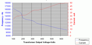
Here's a schematic of the DC chopper and voltage multiplier board. It has an LM555 astable multivibrator with a variable frequency of about 10KHz to 20KHz. The frequency determines the output voltage from the transformer. My prototype puts out 80V-660V RMS depending on frequency. Lower frequency=more voltage.
There's a couple of options built into the board that can be used if you wanted more output voltage. I didn't, but they could be helpful if anyone wanted to use this circuit with a transformer with a lower turns ratio. JP1 selects either 12V regulated or input voltage unregulated to the step-up transformer. Use the input voltage unregulated for more voltage. Use capacitor C17 for more voltage. 0.1uF(100nF) is a good starting point with the astable part values as shown. The values of C1 and C17 may need to be tweaked to resonate with a different transformer.
The X2-X10 pads are not used. They were there to tap the of the voltage multiplier for lower voltages, a remnant of an older design. I connected VSELECT to X10, the highest voltage tap and adjust the output voltage with R4 instead.
Attachments
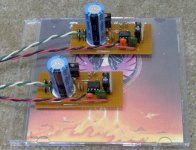
Here's a photo of the back of one of the ESLs with the back cover off.
On the left of the cover is a bank of series connected 6.8K resistors salvaged from my original crossover and behind it is a two-pole six-position switch that forms a variable high pass filter on the narrow stator sections. It will switch between no filter or from one to five series resistors. At first listen to the ESLs with no filter, the midrange seemed a bit too strong. The 6.8K resistors give a subtle adjustment and I'm using a string of three at the moment. The wide stator sections are running fullrange.
The automatic turn on-turn off board is in the middle. To its right you can see the speaker input. Behind the input, but hidden is a 2.5mm connector for DC in from a wall transformer and an LED pilot light to show when the high voltage supply is on. I haven't been shocked yet and the pilot light was a last minute addition to make sure I know when the high voltage is working.
The black and white wires with terminals on the free end will connect to the perforated stators.
Inside the ESL, the new high voltage power supply on the left. There are two boards of resistors near the middle that form a series resistance for amplifier protection. They form a 2 ohm, 20 watt non-inductive resistor. The audio step-up transformer is on the right.
Attachments
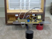
And a photo of the back with everything closed up.
The ESLs at 43" high and 3-3/4" deep was an accident waiting to happen. It was only a matter of time until I bumped one of them or one of our dogs hooked one with a tail and down it went. The block sticking out the back is there to keep the ESL in an upright position.
It's about three pounds of weight cantilevered out 12". Very effective.
Attachments

I've had a chance to listen to the pair together with woofers for the first time this weekend.
Short review:
I really like them. Voices sound lush, drums have a nice attack, and cymbals shimmer. It seems like I hear more detail in the music than I'm used to. Complex music is easier to listen to and I suffer no listening fatigue. After a while I found that I was listening to the music instead of listening to the speakers. The soundstage extends past the speakers and performers seem precisely positioned.
Long review: Everything above is true, but there's still room for improvement.
The ESLs don't like to have a wall behind them. The farther away they are from the wall, the better they sound. Too close and there's some serious comb filtering happening. 24" is too close, but that's about where I'd like them to be. I need to try some wall treatment behind them.
One of the ESLs has some leakage. When it was first turned on, I could hear arcing and a loud hiss from a small area. It's coming from the stator with the diaphragm glued to it. I've been able to partially fix it with small strips of paper between the front and back insulators and reducing the bias voltage. There's still a slight hiss that I can live with for now.
Efficiency is good. Certainly not like a dynamic driver, but my 100wpc amplifier drives them as loud as I want to listen to them.
High frequency dispersion is practically non-existant, typical of a flat-panel ESL. I thought that two 1-1/2" wide panel sections would help that, but physics wins again. It predicted dispersion dropping near 3000Hz. With careful aiming of the ESLs and precise recliner positioning, there's a 3"-4" front to back sweet spot, but what a spot!
I still haven't got a good crossover point between the ESLs and woofers. According to the frequency response of the ESLs, a 12Db/octave filter on the ESLs and a 24Db/octave filter on the woofers at 500Hz should give a smooth transition between drivers. It doesn't work so well. I'm using DSP software on a computer sound card to do the crossover now, so changes are easy to make. At the moment a 300Hz, 24Db/octave crossover sounds better, too high and voices start sounding wrong.
I think the woofers are the problem. They're transmission lines with 8" woofers that are lightly stuffed now and work with a lower crossover frequency, but there's too much midrange coming from the terminus at a 500Hz crossover point. I'll have to add more stuffing to get the bottom end in line and do some more listening.
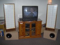
Here is the setup. The ESLs still need grilles.
Short review:
I really like them. Voices sound lush, drums have a nice attack, and cymbals shimmer. It seems like I hear more detail in the music than I'm used to. Complex music is easier to listen to and I suffer no listening fatigue. After a while I found that I was listening to the music instead of listening to the speakers. The soundstage extends past the speakers and performers seem precisely positioned.
Long review: Everything above is true, but there's still room for improvement.
The ESLs don't like to have a wall behind them. The farther away they are from the wall, the better they sound. Too close and there's some serious comb filtering happening. 24" is too close, but that's about where I'd like them to be. I need to try some wall treatment behind them.
One of the ESLs has some leakage. When it was first turned on, I could hear arcing and a loud hiss from a small area. It's coming from the stator with the diaphragm glued to it. I've been able to partially fix it with small strips of paper between the front and back insulators and reducing the bias voltage. There's still a slight hiss that I can live with for now.
Efficiency is good. Certainly not like a dynamic driver, but my 100wpc amplifier drives them as loud as I want to listen to them.
High frequency dispersion is practically non-existant, typical of a flat-panel ESL. I thought that two 1-1/2" wide panel sections would help that, but physics wins again. It predicted dispersion dropping near 3000Hz. With careful aiming of the ESLs and precise recliner positioning, there's a 3"-4" front to back sweet spot, but what a spot!
I still haven't got a good crossover point between the ESLs and woofers. According to the frequency response of the ESLs, a 12Db/octave filter on the ESLs and a 24Db/octave filter on the woofers at 500Hz should give a smooth transition between drivers. It doesn't work so well. I'm using DSP software on a computer sound card to do the crossover now, so changes are easy to make. At the moment a 300Hz, 24Db/octave crossover sounds better, too high and voices start sounding wrong.
I think the woofers are the problem. They're transmission lines with 8" woofers that are lightly stuffed now and work with a lower crossover frequency, but there's too much midrange coming from the terminus at a 500Hz crossover point. I'll have to add more stuffing to get the bottom end in line and do some more listening.
Here is the setup. The ESLs still need grilles.
Attachments
BillH: Very nice job with the construction. It certainly looks less "DIY" than many of the projects I've put together!
On the dispersion issue, perhaps I misunderstood, but I thought you mentioned you were running the wide panels full range. That would certainly cause the high frequencies to beam. I assumed you were going to send the high frequencies just to the narrow panels, and send low pass filtered signals to the wide panels. That would reduce the beaming effect. You could either run the narrow panels full range, or if their resonance frequency intrudes, high pass the signal first.
Sorry if I just misunderstood something...
Few
Hi, Few and thanks.
That was the plan, but it didn't work out. I wasn't able to get a high-cut filter that worked on the wide panels and just went with a low-cut filter on the narrow panels to adjust the midrange a bit. If anybody has an idea on how to make a high-cut filter for the wide panels, I'm very open to suggestions.
You did give me an idea, though. I want to try running only one wide and one narrow panel to see how it sounds and if it has any effect on the dispersion. I'll let you know.
I've got the grilles finished and still need to tweak the woofers and crossover point. It would be done by now, but I had to take a break from the ESLs to finish some painting in our house. 😉
I assumed you were going to send the high frequencies just to the narrow panels, and send low pass filtered signals to the wide panels.
That was the plan, but it didn't work out. I wasn't able to get a high-cut filter that worked on the wide panels and just went with a low-cut filter on the narrow panels to adjust the midrange a bit. If anybody has an idea on how to make a high-cut filter for the wide panels, I'm very open to suggestions.
You did give me an idea, though. I want to try running only one wide and one narrow panel to see how it sounds and if it has any effect on the dispersion. I'll let you know.
I've got the grilles finished and still need to tweak the woofers and crossover point. It would be done by now, but I had to take a break from the ESLs to finish some painting in our house. 😉
Hi BillH-
Have you tried just inserting a resistor in series with the wide panels? Combined with the capacitance of the panel you get a first order low pass response. If the resistor is before the transformer it'll need to tolerate significant current, and if placed after the transformer there will be a big potential drop across it. I've put the resistor after the transformer (the high voltage side) and experienced no trouble, at least when playing at the prototype stage.
Few
- Status
- Not open for further replies.
- Home
- Loudspeakers
- Planars & Exotics
- The ESL Build Thread