Calvin, the d/s spacing is the same on all sections, about 0.055". I'm going to try setting up one speaker with RC filtering and the other with no filter to see how they sound.
I went with the higher R and C values shown because my sim showed excessive current draw with lower R value at high frequencies. As it is now, the sim predicts about 9 watts disappated by the 68K resistors when driven by 100 watts. I doubt they'll ever see that much power, but I designed for the worst case.
Capaciti, interesting note about the phase response. The sim's phase didn't vary by much more than 5 degrees through the frequency range, but it's just a sim so we'll see how it sounds.
Hi,
Normally , you will never get so much power at high frequencies with normal music.This is why dynamic tweeters can be much less powerfull than woofers.
Regards,
Lukas.
Normally , you will never get so much power at high frequencies with normal music.This is why dynamic tweeters can be much less powerfull than woofers.
Regards,
Lukas.
You're right, Lukas. My intent with the sim was to check operation when delivering the maximum voltage I could to the crossover and ESL while running cone woofers from a separate amplifier. I'm assuming a lower efficiency for the ESL than the woofers have and the crossover does cut the voltage a bit, so every volt counts.
My ESL amplifiers max out at 100 watts - 28.3 Vrms into an 8 ohm load. 8 ohms may turn out to be inaccurate when connected to the ESL, but it's a starting point. With a 50:1 step up transformer, that will be 1415 Vrms, 2000 volts peak. The sim was done with two equal power supplies of half the rms voltage referenced to the diaphragm. Each power supply feeds one half of the crossover. In reality, the power supplies are the audio step-up transformer. I wanted to make sure the crossover components could handle the power if I ever ran them loud. 😀
My ESL amplifiers max out at 100 watts - 28.3 Vrms into an 8 ohm load. 8 ohms may turn out to be inaccurate when connected to the ESL, but it's a starting point. With a 50:1 step up transformer, that will be 1415 Vrms, 2000 volts peak. The sim was done with two equal power supplies of half the rms voltage referenced to the diaphragm. Each power supply feeds one half of the crossover. In reality, the power supplies are the audio step-up transformer. I wanted to make sure the crossover components could handle the power if I ever ran them loud. 😀
It has been a busy week, but I found time to get one ESL done to a testing stage.
The stretching jig worked very well. I checked the resonance of the diaphragm with a microphone into my computer's sound card and this software. After I had tightened the film until there were no wrinkles, I tapped the diaphragm in the middle and got a resonance at 17Hz. I had calculated that it should be 21Hz to get the segmented ESL sections to resonances of 89Hz for the larger 4.5" wide sections and 267Hz for the 1.5" wide sections. Tightening the stretcher slowly, the resonance got to 21Hz after four tries.
The screenshot below shows the result. The fundamental resonance is at 21Hz, but as I_Forgot said there are several other resonances above that.
Attachments
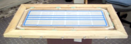
Here's a picture of the stator in the frame with the diaphragm glued on and blue painter's tape masking the area to receive the EC coating.
The diaphragm is glued to the stator with 3M 4693H Plastic Adhesive. After testing on scrap, I went with a thin film of adhesive on the stators, dried, but still tacky. Then the whole stretching jig was lowered on to the stator and the film pressed in place with my fingers. The assembly sat overnight and I cut it away from the waste film and checked the resonances again on all the sections.
The resonances were not what I expected, but if correct, should be fine. The tap test showed 66Hz on the wider sections and the 660Hz on the narrow sections. I'd like to recheck this with an impedance measurement later. I thought the 4.5":1.5" width would give a 1:3 spread, not 1:10.
Attachments
The rest of the assembly went fine no major problems.
So how does it sound? I wish I could tell you.
I fired it up in a darkened room to check for arcs. I couldn't see any, but the neon lamp that indicates charge to the diaphragm stayed on most of the time and I could hear an arc somewhere. It turns out the connection to the diaphragm runs too close to one of the wood frames and was discharging there. I need to take it apart, add some clearance, and try again.
Arcs
Hi Bill,
You might try to enclose the connection point with silicone, or You might use some layers of (one-sided) clear sticky tape on the frame
jauu
Calvin
Hi Bill,
You might try to enclose the connection point with silicone, or You might use some layers of (one-sided) clear sticky tape on the frame
jauu
Calvin
Hi, Calvin.
I need to cut the wood of the frame to get it about 1/8" away from a pair of nuts that hold the diaphragm connection. The frame is removeable so I can't use silicone, but I will take your advice and insulate the frame after cutting it. I have some vinyl tubing that should work.
My wife wants me to paint our dining room before her sister comes to visit on Wednesday, so it may be a few days before I get back to the ESLs.
Hi,
Calvin and Hobbes (You might know the comic?) have a great club named G.R.O.S.S
...
...
...
...
...
Get Rid Of Slimy girlS
If You can afford it financially just set up a TV with 24/7-commercials on and get back to building Your stuff 😀 😀 😀 😀 😀 😀 😀
jauu
Calvin
Calvin and Hobbes (You might know the comic?) have a great club named G.R.O.S.S
...
...
...
...
...
Get Rid Of Slimy girlS
If You can afford it financially just set up a TV with 24/7-commercials on and get back to building Your stuff 😀 😀 😀 😀 😀 😀 😀
jauu
Calvin
Hey Calvin,
what do you think of the torroids from Multi PCB ?
Are those practical for ESL Step-Ups?
What else should be considered when asking for an offer besides the step up ratio (like core material or inductance)?
Thanks!
Greetings
Christian
(You could also email to cfiedler@uos.de)
what do you think of the torroids from Multi PCB ?
Are those practical for ESL Step-Ups?
What else should be considered when asking for an offer besides the step up ratio (like core material or inductance)?
Thanks!
Greetings
Christian
(You could also email to cfiedler@uos.de)
Hi,
besides the StepUp-factor, the tranny needs:
- high primary inductance --> this defines in first place the lower end frequency, the higher mH the lower Flow-3
- low strayinductance --> good coupling of prim annd sec side, defines in first place the upper end frequency, the lower mH the better the coupling, the higher Fhigh-3
- low capacitances --> primary, transformed secondary and interwinding capacitance add up as a shunt capacitance (interwinding beeing of higher importance).
- resistance against arcing --> within the high-voltage-windings as well as between prim and sec side. Normal toroids should be rated at 4kVrms prim-sec min. Double insulation preferable.
- complete windings --> Wire diameter should be chosen such that You end up with complete circles on the core
- interleaved windings --> split up primary and secondary windings in 2 or more windings and interleave prim and sec-windings for good coupling
- windings should be very tightly wound and bandaged --> vacuum drained windings are truely fixed, but capacitance is raised
- core rolled from a thin band of high quality grain oriented material
jauu
Calvin
ps. haven´t tested the Multi-PCB yet, but don´t see any greater probs with those.
Calvin writes: If You can afford it financially just set up a TV with 24/7-commercials on and get back to building Your stuff
Hi, Calvin. 😉 Gotta keep Mrs. H happy. She doesn't mind my speaker building and doesn't quite understand why I do it. Normally she doesn't watch the 24/7 channels, but does try to clear her schedule for Fashion Day on QVC.
I'm doing some troubleshooting tonight. I chiseled out some more room between the frame and diaphragm connection and added insulation between them to stop the arcing. There's still some high voltage leakage between the diaphragm and ground, though.
The neon lamp HV supply mod makes a good tool for diagnosing the HV system. The faster the lamp flashes, the more charge is going to the diaphragm. With the voltage multiplier on the HV power supply set to X2, ~1018V, the lamp flashed 2-3 times a second. At X10, ~5900V the lamp was on constantly and the larger transformer got too warm to run it for more than a couple of minutes. The diaphragm was the only thing connected so far. The stator connections were left hanging in the air.
At X8, ~4720V the power supply arced between the X10 trace and another trace on the board. I'll have to fix that.
By attaching a wire to ground, I could probe with the other end at different points to check for leakage. The final leak to ground is coming from the screws that hold the frame together. I'm not sure why. The conductive coating on the diaphragm stops about 1/8" from the stators and the edge of the screws should be about 1/8" from the stators. The connection to the diaphragm is done with two narrow strips of copper foil near the center of one of the stators. I don't see a path for the HV unless the conductive coating got under the masking tape I used when coating and the 3M adhesive is conductive.
The picture below shows the bottom left corner of the speaker. The ESL panel is sandwiched between wood frames and insulated with white craft foam between the frames and panel. You can see three of the eighteen screws that hold it together. I'm going to try taking it apart and insulating the screws with aquarium tubing.
Attachments

Hi BillH,
1. if you test your voltage you might drop High Voltage significantly. So what you measure might not be the true value.
2. i do not know your D/S spacing, but 4000 Volts appear too much. If you exceed about 2300 Volts per 1mm spacing the air gets conductive and as aresult your neoen lashes constantly. Under humid conditions it even drops down to about 1600 Volts per 1mm.
3. In your picture the stators look poorly isolated. There is no corner rounding visible. I would expect that there are some small needle like edges, which will arc at lowest voltages. Take a look at Martin Logan homepage and watch out forstator pictures. You will recognize thick isolation about 20 mill thick.
4. Your construction is quite impressive, but you are right to isolate the screws. Since the forces to hold the stators are not very high, you coulduse nylon screws.
5. The neon lamp isa great feature. Could describe mor detailed (Neon type........) ?
Capaciti
Blink blink...I shot him down...
Hi,
the indicator circcuit is very simple but effective
R1 is the usual high-valued resistance between cascade and ESL. The capacitor is charged up by the current flowing from the HV-cascade to the ESL-diaphragm. As soon as the voltage over the capacitor reaches the treshold voltage of the Neon bulb (eg. 90V) the bulb fires thereby discharging the cap and the procedure starts again (The voltage of the cap must be higher than the treshold of the bulb). The frequency of blinking indicates how much current is flowing. Ideally there should be no blink after the diaphragm has charged up. In practise a blink every 5-10seconds indicates good isolation. A higher frequency of blinking indicates leakage.
jauu
Calvin
Hi,
the indicator circcuit is very simple but effective
An externally hosted image should be here but it was not working when we last tested it.
R1 is the usual high-valued resistance between cascade and ESL. The capacitor is charged up by the current flowing from the HV-cascade to the ESL-diaphragm. As soon as the voltage over the capacitor reaches the treshold voltage of the Neon bulb (eg. 90V) the bulb fires thereby discharging the cap and the procedure starts again (The voltage of the cap must be higher than the treshold of the bulb). The frequency of blinking indicates how much current is flowing. Ideally there should be no blink after the diaphragm has charged up. In practise a blink every 5-10seconds indicates good isolation. A higher frequency of blinking indicates leakage.
jauu
Calvin
Hi Capaciti and thanks for the suggestions.
True, I can only measure the output of the second AC transformer and that is 360 volts RMS. 360 X 1.414 = 509 volts at the input to the voltage multiplier. The voltage multiplier has taps at X2, X4, X6, X8, and X10.
D/S spacing is about 1.4mm and it has been humid here lately, but I'm seeing leakage even at 1000 volts. I tested it with no connections to the stators and was still getting leakage to the wood frame.
I'm not sure what you mean by poorly isolated, could you explain? There are a lot of needle like edges on the perforated stators. I found it very difficult to remove them all and ended up rounding them over with a wire brush. The edges are still made up of points that are partial holes that remain after shearing to size. If that turns out to be the problem, all I could do now is try to insulate the edges.
The ESL panel is held together with the screws around the edge and horizontal steel round bars that clamp everything together quite solidly. I had thought about using many small nylon screws through the panel to hold it, but didn't have enough room in the center of the panel to do it that way.
I've got most of the day today to see if I can figure out what is wrong. I'm going to try removing the ESL panel completely and check it for leakage outside the wood frame.
if you test your voltage you might drop High Voltage significantly. So what you measure might not be the true value.
True, I can only measure the output of the second AC transformer and that is 360 volts RMS. 360 X 1.414 = 509 volts at the input to the voltage multiplier. The voltage multiplier has taps at X2, X4, X6, X8, and X10.
i do not know your D/S spacing, but 4000 Volts appear too much. If you exceed about 2300 Volts per 1mm spacing the air gets conductive and as aresult your neoen lashes constantly. Under humid conditions it even drops down to about 1600 Volts per 1mm.
D/S spacing is about 1.4mm and it has been humid here lately, but I'm seeing leakage even at 1000 volts. I tested it with no connections to the stators and was still getting leakage to the wood frame.
In your picture the stators look poorly isolated. There is no corner rounding visible. I would expect that there are some small needle like edges, which will arc at lowest voltages.
I'm not sure what you mean by poorly isolated, could you explain? There are a lot of needle like edges on the perforated stators. I found it very difficult to remove them all and ended up rounding them over with a wire brush. The edges are still made up of points that are partial holes that remain after shearing to size. If that turns out to be the problem, all I could do now is try to insulate the edges.
Since the forces to hold the stators are not very high, you coulduse nylon screws
The ESL panel is held together with the screws around the edge and horizontal steel round bars that clamp everything together quite solidly. I had thought about using many small nylon screws through the panel to hold it, but didn't have enough room in the center of the panel to do it that way.
I've got most of the day today to see if I can figure out what is wrong. I'm going to try removing the ESL panel completely and check it for leakage outside the wood frame.
Hi BillH,
the stator need to be perfect without any edges. Professionals perform chemical edging or polishing to round all edges from the manufacturing process.
Even the smallest edges or any other sharp residual will compromise insulation. The smaller and sharper those are, the higher the field density at this location. This results in arcing at low voltages.
If you tell us that there are some visible needles on the perforated plates i think you wont get rid of your problems. The only way is to debur the plates mechanically with a rotating steel brush prior to coating. Make them as rounded and polished as you get them with the brush. If there is just a single needle left it will arc !!
Capaciti
Hi, Capaciti.
There are points on the edges of the perforated steel. I consider the points to be the only drawback to using the perforated material. That doesn't appear to be the problem right now, though. I took the panel out and with nothing connected to the power supply and crossover, the leakage was still there. So the power supply and/or crossover seems to be the problem. I'll remove them from the speaker and see if it still leaks.
There are points on the edges of the perforated steel. I consider the points to be the only drawback to using the perforated material. That doesn't appear to be the problem right now, though. I took the panel out and with nothing connected to the power supply and crossover, the leakage was still there. So the power supply and/or crossover seems to be the problem. I'll remove them from the speaker and see if it still leaks.
Capaciti said:Hi BillH,
the stator need to be perfect without any edges. Professionals perform chemical edging or polishing to round all edges from the manufacturing process.
Capaciti
Hi,
What acids can be used to etch steel ? Probably dilute HCL + something , like H2SO4 ? Also , what do you think about urethane floor warnish for coating ?
Regards,
Lukas.
insulate
Hi,
the edges of perforated steel have to be as soft as possible.
So cutting should be done like this:
Additionally to the thick insulation I added some insulating tape at the edges. That gives very good results.
jauu
Calvin
Hi,
the edges of perforated steel have to be as soft as possible.
So cutting should be done like this:
An externally hosted image should be here but it was not working when we last tested it.
Additionally to the thick insulation I added some insulating tape at the edges. That gives very good results.
An externally hosted image should be here but it was not working when we last tested it.
jauu
Calvin
- Status
- Not open for further replies.
- Home
- Loudspeakers
- Planars & Exotics
- The ESL Build Thread