Hi Calvin,
the insulation in the picture looks great ! Seeing that, i guess there should be no issue with arcing.
Capaciti
the insulation in the picture looks great ! Seeing that, i guess there should be no issue with arcing.
Capaciti
Hi,
the insulation works very well. I´m not afraid to touch both stators with both hands when playing on highest levels 😀
As high capacitive high efficiency designs the panels don´t need much HV to sing anyway, so there´s plenty of safety headroom left.
The sheets are stamped as I stated before and then sand blasted prior to the coating with a powder on polyamide basis by fluidized bed application and additional top coats with an polyurethane laquer.
Having no sharp points at the sheet´s edges and sand blasting accounts for no sharp edges or points. The powder coating (300µm) plus the PU-coating (150-200µm) supply for good electrical characteristics, excellent insulation, a good rounding of the hole´s sides (improves bandwidth) and nice glossy optics.
I admit that this process is not cheap, but the result was worth it.
Curving the sheets gives stability without the need for external bracing. The panel is merely 6mm thick. This way I have a very stable, transparent and safe panel with high efficiency and very high SPLmax.
jauu
Calvin
It's time for an update again. If you remember, I was having trouble with high voltage leakage. I pulled everything apart and started checking each component one at a time.
The problem turned out to be the power supply. There was some stray flux on the pcb that caused arcing and leakage. I cleaned the board again and coated the solder side with a heavy coat of laquer. The next issue was the metal screws, spacers, and nuts I was using to hold the board in place. I replaced the spacers with vinyl tubing and the nuts with nylon. It got better, but still needed some extra insulation on some of the wiring in contact with the high voltage.
After all the repairs, the neon indicator lamp was flashing about once a second with no ESL panel connected. Good enough for now.
I connected the ESL panel and had a constantly on indicator lamp, indicating some major leakage from the panel. I probably need to do some insulating on the perforated stator on the next one. I was thinking of a layer of silicone caulking against the outer edge of the stator to give the sharp points more insulation. Working with high voltage has challenges I never encountered and I'm still learning.
As long as the ESL was together I thought this would be a good time to try it out. It works! 😀 I wan't sure how my amplifier, a 100 watt/channel x 4 Kenwood home theater receiver would handle the load. So I started out at a low volume and brought it up to almost maximum volume and played it for about 5 minutes before shutting the ESL down. I knew one of the transformers on the high voltage power supply would be getting hot because of the leakage from the ESL panel. The receiver was fine.
What a great feeling. I started this project six months ago, routing the stators in a 10°F unheated garage. With the help of you all, it looks like it will be a success. There's a few problems to be taken care of, another ESL to finish, grilles to be made, and final assembly to be done. It has been a good journey.
How do they sound? The first thing that struck me was the low volume. It could be the high voltage leakage, 50:1 audio step-up transformer or low ESL efficiency in general. After I turned it up, and adjusted the woofer volume to match I sat down for a short listen to a couple of cuts from Frank Zappa's "You Are What You Is".
At a woofer/ESL crossover frequency of 225 Hz the ESL integrated well with a TL woofer and the ESL crossover seems to be working. The high end is a bit subdued for my taste, but it's there. A little EQ later should fix that.
The sound is different than anything I've heard before. It was as if I was listening to music come through a speaker rather than from it. I can't wait to hear a pair of these in stereo.
Hi BillH,
congratulations !
You should wait at least 6-8 weeks before you try to equalize the frequence response. Especially the high range will increase its level and clarity by time.
The tensioned membrane is full of small resonances and it needs time and excursion to soften it. In addition efficiency will increase by about 2 dB as well
Capacity
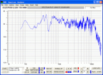
Hi all. I ran a frequency response test on the first ESL panel today. The peak at 100Hz seems to confirm that the stretching tension was correct.
I'm not sure what's causing the dip at 500Hz. The ESL was set up roughly parallel to and 25" from a wall with the microphone 12" from the center of the speaker. 7' to the back wall and 10' to the front wall. The wavelength of sound at 500Hz is about 27", the distance from the ESL panel's edge to the nearest wall, or twice the distance of the narrow dimension of the inside of the ESL. More testing showed that it wasn't caused by the wall.
I'm not sure what's causing the dip at 500Hz. The ESL was set up roughly parallel to and 25" from a wall with the microphone 12" from the center of the speaker. 7' to the back wall and 10' to the front wall. The wavelength of sound at 500Hz is about 27", the distance from the ESL panel's edge to the nearest wall, or twice the distance of the narrow dimension of the inside of the ESL. More testing showed that it wasn't caused by the wall.
Attachments
Well, it looks quite nice.
The suck-out at 200 Hz probably is phase cancellation because of the lack of an enclosure. Putting 'wings' at the back of the esl may give some improvements. I've tried that with my full range esls. Subjectively it improved but I could not perform any measurements. Since you can, it might be an interesting subject to investigate.
Regards, Martin-jan
I dont know if the following have been discussed before.
That is, to build a dedicated Esl amplifier with ordinary output
transistors or fets but including the stepup transformer
in the feedback circuit?
This should eliminate much of the distorsion and nonlinearity
produced by the stepup transformer.
Or?
That is, to build a dedicated Esl amplifier with ordinary output
transistors or fets but including the stepup transformer
in the feedback circuit?
This should eliminate much of the distorsion and nonlinearity
produced by the stepup transformer.
Or?
500Hz
Hi Bill,
as You already mentioned, the wavelength of 500Hz correlates with the panel´s dimensions. You should experience the problem of a standing wave here. As a measurement You might try to add some damping around the inner rim of the panel. You could use for example small strips of foamed rubber (preferably not black!!) thats been sandwiched between stator and diaphragm (cut in irregular shapes like triangle, half-elliptical a.s.o). Another measurement could be to place some silicone drops around the inner rim (in case of a fully built panel)
jauu
Calvin
Hi, all.
It's something I'd like to try. I was trying to match the width of my woofers, but the ESLs ended up to be wider than the woofers anyway.
A reasonably easy to construct and safe amplifier capable of high voltage output seems to be the holy grail of ESL building. I wish I knew more about amplifier design.
I found out it's also the distance from the bottom edge of the ESL to the floor.
MJ Dijkstra writes: The suck-out at 200 Hz probably is phase cancellation because of the lack of an enclosure. Putting 'wings' at the back of the esl may give some improvements. I've tried that with my full range esls. Subjectively it improved but I could not perform any measurements. Since you can, it might be an interesting subject to investigate.
It's something I'd like to try. I was trying to match the width of my woofers, but the ESLs ended up to be wider than the woofers anyway.
SillyCone writes: I dont know if the following have been discussed before.
That is, to build a dedicated Esl amplifier with ordinary output
transistors or fets but including the stepup transformer
in the feedback circuit?
A reasonably easy to construct and safe amplifier capable of high voltage output seems to be the holy grail of ESL building. I wish I knew more about amplifier design.
Calvin writes: as You already mentioned, the wavelength of 500Hz correlates with the panel´s dimensions.
I found out it's also the distance from the bottom edge of the ESL to the floor.
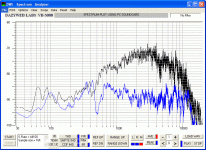
The second ESL is finished. This one has a bead of silicone around all the sharp edges of the perforated stators to try to cut down the high voltage leakage. It helped, but I think there's leakage somewhere else. This one is running with no crossover at all and it's way more efficient than the first one with the crossover.
The picture below shows the frequency response of both panels. The blue trace shows the first panel with crossover and the black trace is the second panel with no crossover. The no crossover version plays loud enough for me, even when listening to one ESL. It's 'brighter' sounding, but a little harsh sounding in the nearfield. Some EQ should take care of that. It sounds better the farther away I get from it.
Both of the ESL's frequency responce graphs show a drooping high end, more about that later. If I had to pick my favorite now it would be the no crossover version.
Attachments
Hi,
Since there is so big difference of efficiency of two panels , something is wrong. I think it might be one of these possibilities(or even something else) :
1. Leakage problem(diapraghm not allowed to charge);
2. Surface resistance too high ( i don't know what coating do you use);
I have had serious problems with pencil graphite , which seems to have too much clay.Even rubbed hard it does not give enough conductivity. Some of test panels were very quet , until i realised what is the problem.
Are you measuring the panels at the same potition in room ?
You should try to measure both panels without a crossover.
Regards,
Lukas.
Yes, flatter but way less efficient. The crossover sure seems to even the response out, though.isn't a flatter freq response what your looking for, the blue is flatter for sure.
It could be the leakage. The more efficient panel has silicone sealant applied to the edge of the stators to stop leakage from the sharp edges. The coating is the same on both panels, so I don't think the surface resistance is the problem.1. Leakage problem(diapraghm not allowed to charge);
2. Surface resistance too high
Yes.Are you measuring the panels at the same potition in room ?
The next step is to try the more efficient panel with the crossover. I just have to swap the panel from one frame to the other. That should determine if it's the crossover or the leakage causing the low efficiency.You should try to measure both panels without a crossover.
I've decided to redo the first panel while it's out and add the silicone sealant to it, too.
I would expect uninsulated sharp edges to cause arcing, which you would probably hear, rather than just some charge leakage that reduces the panel's sensitivity. If you don't hear (or see) arcing, my guess is that the problem is not directly related to the sharpness of edges.
I think I recall you mentioning you have a way to monitor the amount of charge flowing to the diaphragms. Can you discern a difference between the two panels that way? If the less sensitive panel also draws more bias current, that would certianly point toward leakage as the culprit.
Few
I think I recall you mentioning you have a way to monitor the amount of charge flowing to the diaphragms. Can you discern a difference between the two panels that way? If the less sensitive panel also draws more bias current, that would certianly point toward leakage as the culprit.
Few
Hi, Few. The only arcing I've seen has come from the HV supply circuit board, nothing from the panel itself.
The neon lamp indicator flashes whenever the panel charges. With the power supply on and the panel unconnected, there's a flash about once a second. With the more sensitive panel, the flashes are fast, but visible. With the less sensitive panel the lamp looks like it's on continuously so you may be right.
I think I've got everything insulated as well as possible, but can't track down the leakage. The next time I install a panel I'm going to try adding tape as insulation to the edge of the panel assembly as suggested by Calvin earlier in the thread.
Hi all. It's been a busy two weeks and I haven't had much time to work on the ESLs. Just a little bit here and there. The build has entered the final troubleshooting and testing phase. Both panels are assembled and working fine.
I've still got a few problems to sort out on the high voltage power supplies. I've removed the neon lamp from one of them to simplify the wiring and minimize leakage paths. There's a problem with one of the power transformers on each power supply. The setup is 110:12.6 volt transformer --> 5:220 volt transformer --> X2 X4 X6 X8 X10 voltage multiplier. The first transformer gets way too warm after about 5 minutes of use. It seems that its 2.4VA rating is too low. I've got a 15VA transformer to try in the place of the smaller one.
I've done a bit more frequency response testing with different fft software that should resolve out to 21KHz if my microphone is up to it. I found that the response is much smoother on the low end with the ESL on the floor instead of on top of the woofer where it will live. Both the large and small panels have better high frequency response when operated individually. With all panels paralled and operated fullrange the high end droops noticeably.
More bias voltage=more volume, up to a point. The bias supply is variable and I've got the voltage at about 3800 volts. I could get another 700 volts out of the power supply as is, but might get more with the larger transformer. I figure the maximum the panel can take is about 5500 volts.
One more busy day and after that I should be able to get some frequency response graphs for you, do some crossover testing, and see what happens with a larger transformer in place.
I heard the Quad ESL57 bass panels use 18 kV peak-to-peak. A 715B looks like the perfect tube; you don't even need forced air cooling, it being a standard glass tube; it's also pretty cheap.
Hi BillH,
Doesn't small trannies need to have the same secondary winding voltage ? I think that 5:220V transformer is now operating above its voltage , so the core may saturate. By the way , i have sucessfully reassembled a few small transformers(12V:220V) by combining their secondaries onto one core.
The trick is that the windings of these trannies usually are not glued to each other, so you can simply put two 220V sides together.
I think that your bias may be a bit highish , if stator coating is not perfect. Have you tested your stator insulation breakdown voltage ?
Best regards,
Lukas.
I don't know. I'm using the circuit below with a few changes to the voltage multiplier section.Doesn't small trannies need to have the same secondary winding voltage ?
That may be true. If so, the larger VA 110:12.6V transformer may not work either. The 5:220V transformer has never been a problem, though. It doesn't seem to get warm at all.I think that 5:220V transformer is now operating above its voltage , so the core may saturate.
I've just been bringing it up, starting at X2 and looking for arcing in a darkened room and listening for discharge noises on the panels. None so far at X8.Have you tested your stator insulation breakdown voltage ?
Attachments
- Status
- Not open for further replies.
- Home
- Loudspeakers
- Planars & Exotics
- The ESL Build Thread