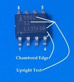
If you are looking at the daughter board right-side up (i.e. all the text is right-dies up), then the "Chip" will be upside down (i.e. writing will be upside down). When installed correctly looking at the board in front of you, the HA5002 will be upside down on the board. Hope that helps.

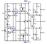
To buzz it out, notice that the collectors of Q22 and Q26 are N-doped silicon, forming PN junctions with the P-doped substrate. So you can diode test between suspected-pin-1 (cathode) and suspected-pin-5 (anode) of the HA5002.
Other ways of finding pin-1 are shown in the photo below.
_
Other ways of finding pin-1 are shown in the photo below.
_
Attachments
@Toadroller
It looks there is notched side of the chip.
It must be '1' pin.
The chip of my 'Norwood' has notched side too.


It looks there is notched side of the chip.
It must be '1' pin.
The chip of my 'Norwood' has notched side too.
I received this in a private message
Would anyone like to answer these questions? The first one can be found on page 10 of the First Watt M2 product manual at firstwatt.com; how about the second one?
[post 1 of the M2x thread says] "As with most First Watt amplifiers, the power output is 25WPC into 8 ohms"
What is the output power using 4 Ohm speakers, is it still 100% class A? I want to know this, because it could limit my choice of loudspeakers.
Would anyone like to answer these questions? The first one can be found on page 10 of the First Watt M2 product manual at firstwatt.com; how about the second one?
I recently upgraded my main speakers from Vandersteen 2C to Vandersteen 3A. The 3As are specified for 6 Ohms nominal, 4 Ohms minimum impedance and 88 dB efficiency. My M2x does a fine job driving these speakers at moderate to not so moderate listening levels. My M2x benefits from an upgraded dual-mono PSU with strong +/- 24V rails.
I would suggest that those wishing to drive lower impedance speakers pay attention to the PSU.
I would suggest that those wishing to drive lower impedance speakers pay attention to the PSU.
1.) 40W.I received this in a private message
Would anyone like to answer these questions? The first one can be found on page 10 of the First Watt M2 product manual at firstwatt.com; how about the second one?
2.)Si! The conduction of the output devices will not change as load impedance changes.
The M2‘s complementary output stage is biased at 1.3A. The amp will remain in Class A into a 4 ohm impedance load for all power levels below 27 watts peak. Above 27 watts, it will transition to Class B, before it clips at 40 watts. In comparison, for an 8 ohm impedance, it will remain in Class A for the entire 25 watts (i.e. until clipping) as it’s max output power is limited by the voltage rails (+/-24 V or thereabouts).
The amp will transition from class A to AB when the peak output current is double the quiescent current or more.
Maximum power output of this amplifier is primarily dictated by the voltage rails of the power supply, however, how much of that power is ‘Class A’ is dictated by the quiescent bias current and load impedance. You do not consider the voltage rails of the power supply in that calculation.
Best,
Anand.
To all newbie builders and veteran builders, I would highly suggest a perusal of these two articles from NP:
Leaving Class A
2019 Leaving Class A Redux
Best,
Anand.
Leaving Class A
2019 Leaving Class A Redux
Best,
Anand.
Hello,
I use a ready-made power supply for the F5V2 with +32/0/-32 VDC, the transformer delivers approx. 900 W.
For a project with FE2022 and M2X, I need +24/0/-24 VDC. I don't want to burn off the excess voltage with resistors.
Asks:
1. Can I operate the M2X with the higher voltage (+/-32V) and correspondingly lower current?
2. Is it possible to use a stepdown converter between rectification and capacitors?
3. Or is it better to use a different transformer with 2x18VAC?
Thanks for the help
Peter
1. No; most of the M2x input stages will not survive +/– 32V operation.
2. Maybe possible but not recommended due to excess heat and space reqirement.
3. A different transformer with 2x18 VAC would be a better solution. Use rectifiers with low forward voltage specification to get +/– 24 VDC
2. Maybe possible but not recommended due to excess heat and space reqirement.
3. A different transformer with 2x18 VAC would be a better solution. Use rectifiers with low forward voltage specification to get +/– 24 VDC
Ahh yes, I forgot about that one and I read it too (clipping, non-linearity, etc)! Thanks for reminding me things that I should know but are not so important 🙂 to me anymore.To all newbie builders and veteran builders, I would highly suggest a perusal of these two articles from NP:
Leaving Class A
2019 Leaving Class A Redux
Best,
Anand.
Last edited:
Is it possible that daughter boards would be working on +/-18 VDC?
I have some spare daughter boards ..so I am considering to use these as input buffer of Class D amp.
I have some spare daughter boards ..so I am considering to use these as input buffer of Class D amp.
Hello
"Houston we have a problem."
Enviroment:
Rail voltage:+/-24V
FETs:2SK1530/2SJ201
The FETs are good, 2SK1530(Vgs=2,29V, I=1,1A) 2SJ201(Vgs=2,37V, I=1,1A)
As recommended R13,R14 = 0,33Ohm, (instead of 0,47R), R11 (221R) shorted, but I tried not shorted also.
1. With the filament protection on, the quiescent current is 0.7A, the offset slowly adjusts to about 20mA. Rv (5k) potentiometer adjusted doesn't change anything.
Resistor R6(47k) has almost no current flow (0.2mA)
2. Turning off the protection, the quiescent current starts to increase immediately, at about 5A (5-7 sec) then I rather turn back on the filament protection, adjusting the potentiometer Rv (5k) does not change anything.
3. I measured the optocoupler diode portion of Q5 with a DMM diode tester (interrupted the circuit by partially unsoldering R11) and it is normal.
I can only take measurements under the filament protection.
All parts are new, but of course I can measure.
I think the regulating the quiescent current does not work and without protection the amplifier would run.
How to proceed, any ideas?
Thank you in advance
Gyuri
Have you mounted the 4N35 optocoupler correct?
It regulates the bias current. You can check if the diode in 4N35 conducts and also if you get a voltage over the capacitor there is in the regulation loop (at the transistor side). Also if the 4N35 is "broken" I think the bias current can go "mad". But I have never experienced a broken 4N35.
It regulates the bias current. You can check if the diode in 4N35 conducts and also if you get a voltage over the capacitor there is in the regulation loop (at the transistor side). Also if the 4N35 is "broken" I think the bias current can go "mad". But I have never experienced a broken 4N35.
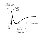
You may have to "fly" with some faith you did it correctly - the M2x will not power on correctly with a DBT (current limiter) in place. See the graphic below, I had a similar question when I first turned my amp on with a DBT and Mark provided this graphic showing the power-up sequence and why the DBT causes issues. This graphic is posted throughout the thread, but I couldn't find a post# to link to.
Attachments
I have quite a few of the 2sk1058 and 2sj162 Renesas lateral fets.
Have been wondering for some time if it's possible and of any benefit to use them in M2X instead of the IRF devices?
Have been wondering for some time if it's possible and of any benefit to use them in M2X instead of the IRF devices?
Thanks for the tip, the fault was caused by incomplete soldering of optoc.Have you mounted the 4N35 optocoupler correct?
It regulates the bias current. You can check if the diode in 4N35 conducts and also if you get a voltage over the capacitor there is in the regulation loop (at the transistor side). Also if the 4N35 is "broken" I think the bias current can go "mad". But I have never experienced a broken 4N35.
The bias now is 1,9A and the offset 10mV and the amplifier is now working with Norwood d.card😃😉
I build monoblocks but the heatsinks are only 3 Unit high and the heat sink is 60 degrees so I have to use a fan (Noctua).
Next step is finished the other channel.
Gyuri
- Home
- Amplifiers
- Pass Labs
- The diyAudio First Watt M2x