
Yes, definitely one concern I have is the location of the amp and the working temp.
I will probably need to change this shelf to a larger one and swap the dynaco/m2X locations, working on top, standing by on bottom shelf.
I will probably need to change this shelf to a larger one and swap the dynaco/m2X locations, working on top, standing by on bottom shelf.
Seeking reviewers for new M2x Input Daughter Card Prototype.
You get to keep the cards forever, in exchange for your quick & honest review.
I've got a new M2x input stage prototype which I happen to like quite a bit. But "Expectation Bias" a/k/a "Proud Parent Bias" probably means that my opinion is flawed. So I would like to solicit other M2x owners, who had nothing to do with the development of the new card, to listen to it with an open mind and review its strengths and weaknesses. If reviewers not named Johnson really like the new card, I'll release the schematic and Gerbers and parts list, etc. If reviewers don't like it, I'll toss it on the Not Good Enough pile and forget about releasing it to the M2x community.
Naturally I'll send you the cards for free and you won't send them back to me after your review is complete.
If you think you'd like to review the new card, send me a private message here on DIYA (called "conversation" in the Forum software) which we'll pretend is an application to receive freebies. Please write at least 2 or three paragraphs, and please include
I'll wait a few days before looking at my PMs, just because many diyAudio members only access the Forum once or twice a week. I want to give those folks an opportunity to review the new daughter cards, same as everyone else. I hope there are people who can review the new cards, quickly.
Thanking you very much,
Mark Johnson
You get to keep the cards forever, in exchange for your quick & honest review.
I've got a new M2x input stage prototype which I happen to like quite a bit. But "Expectation Bias" a/k/a "Proud Parent Bias" probably means that my opinion is flawed. So I would like to solicit other M2x owners, who had nothing to do with the development of the new card, to listen to it with an open mind and review its strengths and weaknesses. If reviewers not named Johnson really like the new card, I'll release the schematic and Gerbers and parts list, etc. If reviewers don't like it, I'll toss it on the Not Good Enough pile and forget about releasing it to the M2x community.
Naturally I'll send you the cards for free and you won't send them back to me after your review is complete.
If you think you'd like to review the new card, send me a private message here on DIYA (called "conversation" in the Forum software) which we'll pretend is an application to receive freebies. Please write at least 2 or three paragraphs, and please include
- What country you live in / where I would ship the cards to
- How many months or years you've been listening to your M2x
- Is the M2x your favorite amp? 2nd favorite? Kinda "meh" but you don't want to trade it away just yet?
- Which input cards you've listened to thus far, and which do you like the most
- "I can commit to listening to the new cards in my M2x right away, and send you my review on or before (date of your commitment)"
I'll wait a few days before looking at my PMs, just because many diyAudio members only access the Forum once or twice a week. I want to give those folks an opportunity to review the new daughter cards, same as everyone else. I hope there are people who can review the new cards, quickly.
Thanking you very much,
Mark Johnson
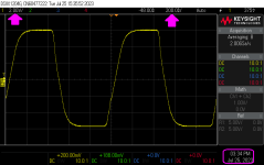
Operating my little daughter card test harness kludge at plus-and-minus 23 volts supply rails. This test comfortably exceeds the Edcor + M2x OPS requirements.
For jollies, measure the slew rate on the photo.
_
For jollies, measure the slew rate on the photo.
_
Attachments
Last edited:
Hi
Slew rate is Voltage change per second.
Voltage: 6divisions from V- to V+, at 2V/div (if i understand correctly the legend)
Time: 1.25division to go from V- to V+, at 200nano sec /div
Slew rate = (6*2)/(1.25*200*10^(-9)) = 48 000 000 Volt/sec roughly...?
(first time doing this, hoping there is not something i misunderstood, so good opportunity to learn from feedback)
Slew rate is customarily answered in Volts/microsecond. So if you did your calculations correctly (it appears so), then the answer would be about 48V/microsecond.
So happy that MJ has a Keysight scope!
By chance, is that a 1Mhz test signal? Frequency = 1/T; where T = 5 period divisions on your scope picture for one full square wave, and each period is 200 nanoseconds.
Best,
Anand.
So happy that MJ has a Keysight scope!
By chance, is that a 1Mhz test signal? Frequency = 1/T; where T = 5 period divisions on your scope picture for one full square wave, and each period is 200 nanoseconds.
Best,
Anand.
Last edited:
New enough to posting that Moderators still control my posts. Please send this directly to Mark's private message in box so I can start a conversation. Thanks, Ed
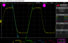
Blue delta_Y = 7.2 vertical divisions = 14.4 volts
Blue delta_X = 1.0 horizontal divisions = 200 nsec
Blue slope = delta_Y / delta_X = ________________ volts per microsecond
Green delta_Y = 7.0 vertical divisions = 14.0 volts
Green delta_X = 1.2 horizontal divisions = 240 nsec
Green slope = delta_Y / delta_X = ________________ volts per microsecond
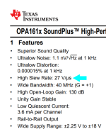
Higher than the slew rate of an OPA1611, the recommended SMD opamp for the M2x Tucson input card.
_
Blue delta_X = 1.0 horizontal divisions = 200 nsec
Blue slope = delta_Y / delta_X = ________________ volts per microsecond
Green delta_Y = 7.0 vertical divisions = 14.0 volts
Green delta_X = 1.2 horizontal divisions = 240 nsec
Green slope = delta_Y / delta_X = ________________ volts per microsecond
Higher than the slew rate of an OPA1611, the recommended SMD opamp for the M2x Tucson input card.
_
Attachments
First of all, I would like to thank Nelson Pass for publishing M2 , and Mark Johnson for the daughter cards and useful advice.
My own M2x is almost finished, just some minor mechanical work to do.
Parameters per channel:
Monoblock design
300VA toroidal transformer
2x24V DC
128000 uF (4x22k-R-4x10k)
1.7A bias current
2SK1530/2SJ201 Mosfet transistors
Norwood daughterboard
Specials, sound quality tunning
1. Separate transormator per channel and dual stabilized power supply for Norwood daughterboard (clear sound quality improvement compared to normal power supply)
2. Dual power supply (ebay - quality of capacitors questionable)
Changed the capacitors to Nichicon KG S.T. and Muse and the difference was even more impressive.
3. Omitting Zener diodes
Thevoltage of the stabilized power supply (+/-15V) is sufficient to feed the Norwood directly, I skipped the Zener diodes. This change did not result in any improvement or I did not hear any improvement.
4. Norwood C7 220uF Nichicon bipolar capacitor
Their crossover is also positive and audible in my opinion.
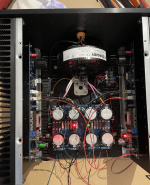
I've been listening for about 1 month now, but I like it so much that it's finally worth it to replace my old speaker with a more serious piece (Audio Solutions Figaro B). My hi-fi chain has been taken to the next level (source Ian Canada Q3+Reclock, dual DAC, LL I/V, Uc + Salas-L and batteries).
I attach some pics, here is still using to rail Norwood only one transformer, but it's too big, won't fit in the box, will be replaced with low profile and lower power.
I still want to bypass the Nichicon capacitor on the M2 main panel with another better quality bypass capacitor.
Interesting fact:
I tried powering the Norwood with LiFePo 26650 batteries (3-3) Crystal clear..., of course not usable in practice.


My own M2x is almost finished, just some minor mechanical work to do.
Parameters per channel:
Monoblock design
300VA toroidal transformer
2x24V DC
128000 uF (4x22k-R-4x10k)
1.7A bias current
2SK1530/2SJ201 Mosfet transistors
Norwood daughterboard
Specials, sound quality tunning
1. Separate transormator per channel and dual stabilized power supply for Norwood daughterboard (clear sound quality improvement compared to normal power supply)
2. Dual power supply (ebay - quality of capacitors questionable)
Changed the capacitors to Nichicon KG S.T. and Muse and the difference was even more impressive.
3. Omitting Zener diodes
Thevoltage of the stabilized power supply (+/-15V) is sufficient to feed the Norwood directly, I skipped the Zener diodes. This change did not result in any improvement or I did not hear any improvement.
4. Norwood C7 220uF Nichicon bipolar capacitor
Their crossover is also positive and audible in my opinion.
I've been listening for about 1 month now, but I like it so much that it's finally worth it to replace my old speaker with a more serious piece (Audio Solutions Figaro B). My hi-fi chain has been taken to the next level (source Ian Canada Q3+Reclock, dual DAC, LL I/V, Uc + Salas-L and batteries).
I attach some pics, here is still using to rail Norwood only one transformer, but it's too big, won't fit in the box, will be replaced with low profile and lower power.
I still want to bypass the Nichicon capacitor on the M2 main panel with another better quality bypass capacitor.
Interesting fact:
I tried powering the Norwood with LiFePo 26650 batteries (3-3) Crystal clear..., of course not usable in practice.
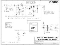
Perhaps even better than a dedicated power supply to feed both channels' front end cards, is to install a dedicated voltage regulator (or two voltage regulators in series!) on each front end card. Now the front ends are isolated from main amp channel power supply noise, and they are also isolated from each other.
Most M2x daughter cards don't have enough room for this (but see "IPS7" for an exception). However Lottery-VFET and Ship Of Theseus front end cards allow abundant space for on-card supply regulation and filtering. Check out "Dreadnought" in the diyAudio Store. And here are two more examples from the Ship Of Theseus. Have your circuit designer friends put one of them or both of them into a simulator and measure the power supply rejection ratio. Cowabunga.
_
Attachments

"48V/microsecond" yes and i was in fact going from an "average slope" (=not the slew rate def) to go from V- to V+ (red lines on the attached image)
Whereas the real best instantaneous slope = slew rate are depicted by MJ
Blue slope = 72 volts per microsecond
Green slope = 58.3 volts per microsecond
Thanks for the little homework

Whereas the real best instantaneous slope = slew rate are depicted by MJ
Blue slope = 72 volts per microsecond
Green slope = 58.3 volts per microsecond
Thanks for the little homework
Often 10% to 90% is used for "rise time" definition?
Only important if "rise time" is compared to other devices........to know the exact definition.
Only important if "rise time" is compared to other devices........to know the exact definition.
barbosas:
Either you are a pilot, or a sailer. My guess from Portugal, a sailer.
Power Supply left and right channels-Port Red-Starboard Green.
Quite Brilliant Idea!!!
Either you are a pilot, or a sailer. My guess from Portugal, a sailer.
Power Supply left and right channels-Port Red-Starboard Green.
Quite Brilliant Idea!!!
Attachments
Last edited:
Having built my M2x with two different power supplies, I can definitely say it sounds better with separate supplies for each channel. In its current form, each channel has a separate 250VA transformer feeding a PSU with synchronous rectification and a CLC filter. There is still a small amount of 120 Hz hum that is noticeable with my ears close to the speaker. This seems to be magnetic coupling between the power transformer and the Edcor signal transformer. Nevertheless an improvement over a single 400VA transformer enclosed in a matching steel case from Antek feeding both channels.
Once each channel is fed from a separate PSU, the next question is whether to build a shield for the Edcor, to employ extra filtration / regulation for the input signal buffer, or maybe both. We should probably note that FirstWatt built M2 amplifiers include shielding for the Edcor transformers.
For my part, I am inclined to try some shielding, then maybe a variation of one of the opamp input stages (inherently high PSRR). Then look at ways of adding capacitor supply filtration near the input stage.
I made a Mu-metal box which fits over the Edcor same as others have reported earlier in the forum (search Mu-metal in this thread). I also have the steel cover on the Antek. No noise can be heard with an ear to the speaker at high input gain. I can't prove that what I mention is the reason but it's certainly worth trying.

One diyer's noise may be another diyer's silence, depending on their speaker's sensitivity.
A good measuring stick is FFT. I usually output an 1kHz signal at 1W into 8R and see how low the noise is relative to the 1kHz signal. That takes the speaker sensitivity out of the equation when comparing amplifier noise before and after modifications.
A good measuring stick is FFT. I usually output an 1kHz signal at 1W into 8R and see how low the noise is relative to the 1kHz signal. That takes the speaker sensitivity out of the equation when comparing amplifier noise before and after modifications.
Ben, if you're worried only about magnetic coupling between power transformer and Edcor interstage coupling transformer(s), you can do the FFT test with shorted inputs. No need for 1 kHz signal generator, no need for 8R dummy load resistors, no need to carefully dial the amplitude until you're getting 1.00W @ 8R. Just run the FFT with RCA shorting plugs on the inputs, and look at the magnitude of 50/100/150/200/250 Hz spikes (EU), or 60/120/180/240/300 Hz spikes (USA).
- Home
- Amplifiers
- Pass Labs
- The diyAudio First Watt M2x