Why so many reasons to get an oscilloscope??? I can't find any against. Except I can't pick a journyman's unit that I can afford. Or buy best spec. for audio.
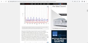
With my hobby REW/Focusrite FFT rig that I use, the Focusrite gain is adjustable, and the amount of gain at any setting is unknown to me. So I input a reference signal at a known level so that the noise can be measured relative to it. The results can then be compared. Without the reference signal, the magnitude of the spikes is unknown to me.
Perhaps there is another way of determining the magnitude, but the reference signal method is simple enough and works for me.
Or perhaps my reasoning is all wrong.
Perhaps there is another way of determining the magnitude, but the reference signal method is simple enough and works for me.
Or perhaps my reasoning is all wrong.
I second Ben‘s approach in post #6442. The measurement using a reference signal works even if some time has passed between different measurements / configurations, and one has their measurement rig used for other things in between.
You could do relative measurements with the Focusrite without a reference signal, but then you have to make sure that gain, configuration etc. is the same between the two measurements. And with the Focusrite, I haven‘t thought of another way to repeat a gain setting than to put some sticky tape next to the knob and mark a setting on the tape. Not a very scientific way, but probably works if you do two measurements in close succession without altering anything in your measurement rig or in the operating parameters of the DUT / amp.
Should be fine enough if you only move some magnetic shielding pieces around, but I wouldn‘t trust it if I had a week between measurements.
Regards, Claas

I made a couple tweaks to my M2x. My re-capped Threshold CAS-2 and modified F6 have served as inspiration for achieving better sound from the M2x.
I found a reasonably priced roll of high permeability cobalt alloy metal sheet to address the issue of magnetic field coupling between the power transformers and Edcor signal transformers. So far I have applied metal strips over the tops of the Edcors, securing them in place with adhesive copper tape. I have enough material remaining to wrap a band around each of the power transformers.
After spending some time reviewing the original M2 thread, I decided to try a couple more adjustments. I changed the Source resistors R13 and R14 to 0.45 Ohm, 1% to get lower output impedance and better matched current between the push-pull devices. I also changed R11 to 200 Ohms to provide more current to the LED side of the 4N35 optocoupler. These are small incremental changes, but I didn’t feel the need to make a big change to the sound of the amp. The new bias current is 1.38 Amps.
The high permeability shields over the Edcors have reduced the hum to a level that is just detectable with my ear very close to the speakers. Probably not worth the extra effort to wrap the power transformers. On the other hand, the soundstage presentation and transparency have been noticeably improved. I spent a very enjoyable afternoon listening to the amp with a few of my favorite recordings. My M2x sounds more like my F6, with similar height, width and depth to the soundstage. The transparency and physical presentation of acoustic and electric instruments is much like the CAS-2. This is a wonderful combination.
Note that my F6 and M2x both use variations of a diamond buffer as their input stage.
It is really interesting to discover how relatively small changes to a circuit can have an important impact. In the world of DIY audio we are frequently chasing sonic improvements from all manner of tweaks and modifications. Much of my time has been spent on improving the power supplies of the various amps I have built, and this has been time well spent. The re-build of my M2x a while back was all about the power supply – moving to dual-mono and synchronous rectification with a CLC filter. That made a big improvement to the sound of the amp. The latest changes were to the amp circuit itself.
It was necessary to reread about the first 60 pages of the original M2 thread before I felt confident in making just a couple careful modifications. The goal was to bring the sound of the M2 up to the level of my F6, following recent improvements to that amp that were inspired by listening to the CAS-2. The big Vandersteens that now occupy my listening space have proven to be more demanding than their earlier siblings. I wanted to increase the M2 bias current to help drive the lower impedance of the 3A Signatures, and found that this could be accomplished by lowering the output impedance at the same time. I was also looking for a firmer sense of instrument placement in the soundstage, and thought that increasing the current through the 4N35 optocoupler might help with that. The modifications to the Source resistors and R11 proved to be synergistic.
It was necessary to reread about the first 60 pages of the original M2 thread before I felt confident in making just a couple careful modifications. The goal was to bring the sound of the M2 up to the level of my F6, following recent improvements to that amp that were inspired by listening to the CAS-2. The big Vandersteens that now occupy my listening space have proven to be more demanding than their earlier siblings. I wanted to increase the M2 bias current to help drive the lower impedance of the 3A Signatures, and found that this could be accomplished by lowering the output impedance at the same time. I was also looking for a firmer sense of instrument placement in the soundstage, and thought that increasing the current through the 4N35 optocoupler might help with that. The modifications to the Source resistors and R11 proved to be synergistic.
I am gathering parts for a long overdue M2 build. I noticed I have 2 x IRFP9240 in my drawer, so that is sorted. I don't have any IRFP240 but have 50 x IRFP044 I bought some years ago. Can I use the 044 and 9240 together in the M2 or should I get some 240s?
I made a couple tweaks to my M2x. My re-capped Threshold CAS-2 and modified F6 have served as inspiration for achieving better sound from the M2x.
I found a reasonably priced roll of high permeability cobalt alloy metal sheet to address the issue of magnetic field coupling between the power transformers and Edcor signal transformers. So far I have applied metal strips over the tops of the Edcors, securing them in place with adhesive copper tape. I have enough material remaining to wrap a band around each of the power transformers.
After spending some time reviewing the original M2 thread, I decided to try a couple more adjustments. I changed the Source resistors R13 and R14 to 0.45 Ohm, 1% to get lower output impedance and better matched current between the push-pull devices. I also changed R11 to 200 Ohms to provide more current to the LED side of the 4N35 optocoupler. These are small incremental changes, but I didn’t feel the need to make a big change to the sound of the amp. The new bias current is 1.38 Amps.
The high permeability shields over the Edcors have reduced the hum to a level that is just detectable with my ear very close to the speakers. Probably not worth the extra effort to wrap the power transformers. On the other hand, the soundstage presentation and transparency have been noticeably improved. I spent a very enjoyable afternoon listening to the amp with a few of my favorite recordings. My M2x sounds more like my F6, with similar height, width and depth to the soundstage. The transparency and physical presentation of acoustic and electric instruments is much like the CAS-2. This is a wonderful combination.
Note that my F6 and M2x both use variations of a diamond buffer as their input stage.
I understand the argument about the 1% resistors but original resistor value is 0.47 Ohm so 0.45 is not much of a change to get lower output impedance?
You were not tempted to try out 0.33 Ohm or 0.22 and then just keep the 221R for the optocoupler LED? .....to crank up the bias a bit?
I wonder if someone has tried such a tweak?
I use large 5U chassis so extra heat is not a problem in my case......and PSU can take it.
It could be a future experiments. My M2X mono blocks are at the shelf in the moment.
I have upgrades for the chassis. I got the M3 frames for it so I can upgrade from self-cutting screw to M3 hex (future project).
The parts I had on hand were 0.45 Ohm. I might have preferred 0.40 Ohm, but didn’t want to wait for an order to arrive. My M2x is in a relatively small chassis, so I need to be careful with power dissipation.
The results were positive, and I can recommend others try this as well.
The results were positive, and I can recommend others try this as well.
I wonder how low you can go in source resistors and still have a stable amplifier.
Trial and error maybe?
Trial and error maybe?
The optocoupler biased output stage was a US Patent, application filed in 1987 and patent granted in 1988. A mere thirty five years ago. US Patent # 4,752,745 granted to Nelson S. Pass and assigned to Threshold Corporation of Auburn, California, USA.
In applications like this, I use the transconductance figure of merit (and others) to gauge possible matches between different Mosfets.I am gathering parts for a long overdue M2 build. I noticed I have 2 x IRFP9240 in my drawer, so that is sorted. I don't have any IRFP240 but have 50 x IRFP044 I bought some years ago. Can I use the 044 and 9240 together in the M2 or should I get some 240s?
The IRFP044 has a much higher transconductance than than the IRFP240, which is already a difficult match for the IRFP9240. A better matched pair would be the IRFP240 and the IRFP9140. Several of us have built our M2x with this set of devices.
I wouldn’t trust LTSPICE to model the circuit accurately
with some mileage we already have, M2 OS can be calculated on napkin

By "up" I assume you mean the mosfet at position q1 (the 240) on the original m2 schematic and by "down" q2 (9240)?
If so, then by your reasoning the 044 combined with a 9240 would cause 2nd dominant with negative phase. Correct?
I recently (finally) completed the H2 and tried it with my vfet lottery amp (unmodified) on very revealing and analytical avalon studio pro monitors and absolutely love the result.
I have not had time to experiment with different caps (old silmic 2 in there now), replace the walwart psu, play with the potentiometers or measure the distortion, but it has shown me that that I like 2nd dominant. It also showed I need to dust off my BA3 preamp, add a decent psu (now just using crc) and play with p3!
Perhaps for the m2 it is worth it to try the 044 together with the 9240 and see how it sounds 🙂
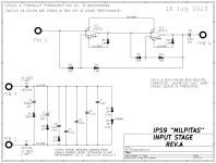
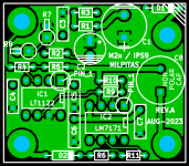
THE MILPITAS INPUT STAGE FOR M2x
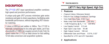
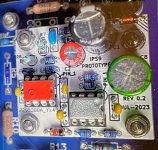
It's a delight to present the newest member of the M2x InPut Stage daughter card family: MILPITAS. This is my ninth diyAudio IPS card, so its alt-name would be "IPS9". The principal semiconductor device on the board is made by Linear Technology's fab in Milpitas, California.
Milpitas is a thru-hole-only upgrade of the Norwood card that ships in the M2x board set from the diyAudio Store. Milpitas intentionally uses readily available, on-the-shelf-today ICs, arranged in the same general topology/architecture as Norwood. Unfortunately the Norwood chips are on 45 week backorder at the moment.
Both Norwood and Milpitas are composite amplifiers, having two individual amplifiers enclosed within the same global negative feedback loop. Composite amplifiers are notoriously prone to oscillation; to avoid this, designers must carefully tailor the frequency response of each individual amp in the composite pair. Thus "Opamp rolling" within a composite amplifier is certainly not a good idea, as it will lead to degraded stability or oscillation. That's very bad for your tweeters.
The Milpitas circuit includes capacitors for power supply bypass (C1-C7) and for AC coupling (C8). But it has no capacitors for frequency compensation. No "Miller" capacitors, no "Lag" capacitors, no "Pole Zero" capacitors, none. Instead, the individual opamps within the composite are carefully selected for complementary frequency responses, reducing phase lag around the entire NFB loop at all frequencies below the gain crossover. The topology looks a bit unusual, and appears in very few textbooks, but it works well in practice. See the scope photo in post # 6424-6428 of this thread for more.
CONSTRUCTION NOTES
Milpitas uses 1/6 Watt resistors everywhere except R1, R7, and R8. 1/6 Watt parts are significantly smaller and make PCB layouts more compact. However, R7 and R8 dissipate plenty of heat, so 1/6 watt resistors aren't beefy enough for those. But what about R1? R1 dissipates ZERO power: why 1/4 Watt? The pedestrian answer is, Mouser doesn't carry any 1/6 Watt resistors with values below 1 ohm. So we buy a 1/4 watt resistor for R1 and mount it vertically.
BTW you really want a Mega328 Component Tester or a good quality digital multimeter when you're building Milpitas, so you can measure each resistor's value before stuffing and soldering. Attempting to read the color codes on 1/6 Watt resistors will drive you nuts.
The Detailed Parts List attached below, includes a line-item for DIP sockets. I struggled with this; the circuit works better when the DIPs are soldered directly into the PCB with no socket. And DIP sockets may encourage misguided builders to attempt opamp-rolling, which would be disastrous. On the other hand, sockets allow builders to easily remove the not-inexpensive chips from a failed or mis-assembled Milpitas board, and use them again in another attempt. So, with reservations, I included socket part-numbers on the Parts List. But I hope you don't use them. (Full disclosure: I did install sockets on the IPS9 prototype boards sent out to reviewers for listening evaluation. This was merely conservatism: if IPS9 sounds great WITH sockets and all of the parasitics they introduce, it will definitely sound great without sockets).
I suggest you take photographs of your bare PCBs before you start assembly. Then as you install components and they begin to obscure the text on the PCB silkscreen, you can view your photos to remind yourself: what goes where, which is the "+" terminal, etc.
LISTENING EVALUATION(S)
Three pairs of IPS9/Milpitas boards were sent out to volunteer reviewers, three weeks ago. Each reviewer installed the boards into their M2x amplifiers and noted the strengths and weaknesses of the new input stage. Overall their evaluations were enthusiastic, and I've encouraged those reviewers to post their written reviews here in this M2x thread, if they are comfortable doing so. My executive summary of the three reviews is: 3X two thumbs up, overall average score was 1.3 where 1.0 is best-possible score and 9.0 is worst-possible score. "1" means best sounding of all M2x input cards and "9" means worst sounding of all M2x input cards.
However, M2x is a platform for experimentation which allows each builder to form their own opinions, uninfluenced by other people. Others have their own preferences, and you have yours. Try some IPS cards and listen for yourself, you may violently agree or violently disagree with what other M2x owners have to say. Don't let anyone talk you out of listening to whatever pleases YOU the most.
FURTHER DISCUSSION OF MILPITAS / IPS9 IN THIS THREAD
I'd like to encourage members to address inquiries and questions about Milpitas, to everyone on diyAudio who reads this Forum thread. Two hundred fifty thousand heads are better than one! So please if you're tempted to start a message with the words "Mark please tell me fact X", I recommend you reword the message, and say instead "Dear diyAudio members, I need assistance learning about X, can you help me?" Now you've tapped into the collective wisdom of the entire membership, which can't hurt and probably helps a great deal. INDEX377 INDEX377 INDEX377 . I'm quite confident that any post which begins with the word "Mark" will receive less attention than you would prefer, especially if you're in a hurry.
BUILDING SOME MILPITAS INPUT STAGE CARDS OF YOUR OWN
The PCB Gerber files for board fab are attached below. I recommend you use the price quotation service www.pcbshopper.com to get an idea of PCB cost, for your ship-to address in your country. Milpitas is 40x35mm, two layers, and I suggest you get quotes for 11 business days shipping, as that seems to be the sweet spot of price versus delivery delay. Then you can refine the quotes after getting initial ballpark estimates, to see how much extra you must pay to get faster shipping. Or to see how much you can save by accepting an extra week of delay.
Also attached is a Detailed Parts List showing what's important and what's not important, when you select parts for Milpitas. This includes recommended part numbers from Mouser.com. I also recommend you train yourself to use the super handy website www.octopart.com to check prices and available-stock-on-the-shelf at dozens of distributors, all at once. You can see who has the lowest price, who has the biggest stockpile, and who offers the best discounts for purchasing in quantity. You'll love octopart.
If you do build Milpitas cards and install them in your M2x, you'll be listening thru 200 Megahertz opamps (!). Not unity gain buffer chips; opamps. 200 MHz opamps. Almost certainly, none of your audio buddies can make the same claim. You'll have bragging rights.
Attachments
-
 datasheet_blurbs.png33.8 KB · Views: 1,506
 -
 image_file_schematic_Milpitas.png33.2 KB · Views: 629
 -
 Early_Prototype.jpg381.2 KB · Views: 2,382
 -
 revA_Gerbview.png19.3 KB · Views: 547
 -
IPS9_Milpitas_Schematic_RevA.pdf25.4 KB · Views: 260
-
Gerbers_IPS9_Milpitas_RevA.zip30.6 KB · Views: 227
-
PartsList_ips9_Milpitas_RevA.zip6 KB · Views: 251
Last edited:
Four Thousand One Hundred Volts per Microsecond slew rate??

Also - https://gifdb.com/gif/wow-chris-pratt-9x6sskiocxfk8vhr.html?embed=true
Also - https://gifdb.com/gif/wow-chris-pratt-9x6sskiocxfk8vhr.html?embed=true
Last edited:
- Home
- Amplifiers
- Pass Labs
- The diyAudio First Watt M2x