Pass DIY Addict
Joined 2000
Paid Member
Ha - I’ve always been amazed at what I can see in an image that I didn’t see looking directly at it. I always ask myself, “How did I miss THAT???”
hello,
I am new here but would like to build this amp.
Sorry for my silly question but is it available in kit with PCBs and all electronic componets? (especially edcor pc600/15k and paired active parts)
Shipping to Hungary...
Thanks
I am new here but would like to build this amp.
Sorry for my silly question but is it available in kit with PCBs and all electronic componets? (especially edcor pc600/15k and paired active parts)
Shipping to Hungary...
Thanks
No, it is not available as a kit from the DIYA store.
However, there are full bills of materials posted, some that include part numbers from popular electronics retailers, to make things easier.
However, there are full bills of materials posted, some that include part numbers from popular electronics retailers, to make things easier.
Ok, now I understand how the mosfets were mounted. That looks much better than I was imagining 😉
I suggest horizontal pcb next time 😉
No, it is not available as a kit from the DIYA store.
However, there are full bills of materials posted, some that include part numbers from popular electronics retailers, to make things easier.
this thread is quite long. Do you happen to remember approximately when was it posted?
Thanks
oidu you can go to the DIYaudio store tab at the top of the page and look under boards > power amps > MX2. In the description there are links to the BOM, Schmatic and build thread. All the information you need.
First page mate...this thread is quite long. Do you happen to remember approximately when was it posted?
Thanks
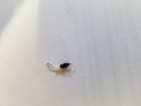
Eric: removed the hair from the position you noted and it made no difference -- the left channel is hosed. Attached is a picture of R12 -- the resistor that burned almost in half. Would like to know what other board component(s) could have caused this or whether it could be the result of the RCA short. If anyone has any suggestions, thanks.
Am ordering replacement components for the board and would like to make sure I get all of the possible offenders replaced. Can this type of failure be the result of the transformer?
Am disinclined to try the RCA DC offset adjustment on the other channel because of the first failure. Can any one this site tell me how they have succeeded with this calibration?
Waiting for Mouser...a common state.
Attachments
While there are discussions as to whether one is better that the other at the frequencies we use in amps, like many things in audio there is no consensus. So the advantage tilts to solid internal wiring for the ACA because it is much easier to insert in small holes in switches, etc. and to bend and organize neatly so higher amperage cables aren’t next to signal level, etc.
An umbilical cable from one chassis to another is going to be flexed more that anyone would think over the decades so the chance of a solid conductor fracturing is actually reasonably high…amd yeah, hard to terminate.
An umbilical cable from one chassis to another is going to be flexed more that anyone would think over the decades so the chance of a solid conductor fracturing is actually reasonably high…amd yeah, hard to terminate.
6L6: Will certainly do so and can you tell me why? The ACA amps I have been building use 24awg solid wire for the power supply connections to the circuit boards and from this I assumed there was some advantage.
Thanks for your response.
Last edited:
Found the problem with the trouble board. The two mosfets had been switched -- user error. Will redo them and replace with upcoming parts from Mouser. Wonder how many other components this could have affected. Some of the resistors were certainly ruined,
Variac: Ended up using the 18awg fine stranded cable recommended by Eric and it works just fine. No problems with the PSU except it outputs 25.74 volts +- rather than 24. Hope this makes no difference.
Variac: Ended up using the 18awg fine stranded cable recommended by Eric and it works just fine. No problems with the PSU except it outputs 25.74 volts +- rather than 24. Hope this makes no difference.
To get a ballpark estimate, look up the First Watt M2 owner's manual on the First Watt website. It's got a specification table which lists the total power drawn from the AC mains.
Then make the conservative assumption that ALL of that power is dissipated in the two heatsinks. Assume there is no power dissipated in the toroidal transformer, no power dissipated in the rectifier bridges, and no power dissipated in the CRC filtering networks on the PSU board. {these assumptions are wrong, of course, but they are wrong in the conservative direction}
Assume half of the power is dissipated in the "Left Channel" heatsink, and the other half is dissipated in the "Right Channel" heatsink.
Finally, look up the thermal specifications of your 2U heatsink. Find out the temperature rise (above ambient air temperature), when you connect it to a heat source of XXXXX watts.
Vunce: Will let you know. Have AC Infinity fans that I use for my Emotiva amps and can borrow one for the M2X should I get it running. And Paul has recommended a thermometer ordered from Amazon that will tell me the heatsink and mosfet temps.
BTW, have been able to check the one channel working to see if the outboard PSU concept works and, so far, so good. There appears to be no noise in the channel at all. The sound quality is not great but have not yet adjusted the DC offset.
BTW, have been able to check the one channel working to see if the outboard PSU concept works and, so far, so good. There appears to be no noise in the channel at all. The sound quality is not great but have not yet adjusted the DC offset.
I always love your teach a man to fish approach of answering a question and I learned quite a bit from this post. It isn't intuitive where the information on thermal specifications exists so I'm linking to the page here. C/W is presumably degrees centigrade rise above ambient per watt dissipated by the heatsink. Bottom line is the 2U is at best a marginal choice for the M2x.To get a ballpark estimate, look up the First Watt M2 owner's manual on the First Watt website. It's got a specification table which lists the total power drawn from the AC mains.
Then make the conservative assumption that ALL of that power is dissipated in the two heatsinks. Assume there is no power dissipated in the toroidal transformer, no power dissipated in the rectifier bridges, and no power dissipated in the CRC filtering networks on the PSU board. {these assumptions are wrong, of course, but they are wrong in the conservative direction}
Assume half of the power is dissipated in the "Left Channel" heatsink, and the other half is dissipated in the "Right Channel" heatsink.
Finally, look up the thermal specifications of your 2U heatsink. Find out the temperature rise (above ambient air temperature), when you connect it to a heat source of XXXXX watts.
40mm Heatsinks – diyAudio Store
Would like to state once again that there is another reason for using a 3U or higher heatsink -- as I have mentioned above. The 2U heatsink is just a little too small for the M2X board and Mosfets themselves. Attachments above show how tight this fit is and that it requires altering the rails.
Pass DIY Addict
Joined 2000
Paid Member
Good find, Craigl59! Covering the mosfets with big washers makes visual inspection difficult to perform. I was going to suggest next that you make sure your mosfets are actually electrically isolated from the sink. Using soft silpads (kerathem) leaves you vulnerable to tiny metal shavings from hole tapping that can pierce the pad and cause a short. Also, be sure to deburr the hole after drilling to get rid of the raised lip that will result. This is an invisible problem when it happens. I’ve started using ceramic aluminum oxide pads and thermal paste instead of silpads. They are thick and rigid, transfer heat better, can’t be pierced, and cost less. Check out Mouser for part number 4180G. You can also get them on ebay for less money. Since you are rebuilding, it’s worth the effort. Silpads cannot be reused.
Mount your mosfets to the sink first. Take your dmm and check for continuity between the center pin (tied to the metal pad on the back) and the sink. Should be open circuit. Any resistance reading at all means you have a problem -remove and inspect. Only when you are SURE there are no shorts should you mount the mosfets to the board.
I managed to reverse a few power transistors with my very first amp build (my a40). Made a bit of a mess of the pcb. Bit after replacing a few bits here and there, its still works great 20 years later!
I have one channel of an M2x running on the bench with lab supply connected for bi-polar output reading 32 watts on channels 1 and 2. Do I sum the wattage of channel 1 and channel 2 to get the actual consumption?
I'm trying to calculate temperature using Ohm's Law where V=temperature above ambient, I = power (watts), and R = thermal resistance. Am I on the right track?
I'm trying to calculate temperature using Ohm's Law where V=temperature above ambient, I = power (watts), and R = thermal resistance. Am I on the right track?
Yes, channel 1 of your power supply is delivering 32 watts to the single M2x board. Channel 2 of your power supply is delivering another 32 watts to the single M2x board. Thus your M2x board is receiving 32+32 = 64 watts of electric power, and converting that power into heat.
For heatsink thermal calculations,
Temperature_Rise (in degC) = Watts_dissipated * Thermal_Resistance (in degC per watt)
{don't forget that heatsink temperature = temperature rise plus ambient air temperature }
For heatsink thermal calculations,
Temperature_Rise (in degC) = Watts_dissipated * Thermal_Resistance (in degC per watt)
{don't forget that heatsink temperature = temperature rise plus ambient air temperature }
- Home
- Amplifiers
- Pass Labs
- The diyAudio First Watt M2x