Here is Mark's advice on how to run an amplifier without daughter cards.If you do all three of these actions before powering up an M2x amp channel card
- completely remove the input stage daughter card
- short the IPS daughter card input (bolt #2) to the IPS daughter card output (bolt #4) with many figure-eight wraps of copper wire
- insert a shorting plug into the RCA input jack, which connects INPUTSIGNAL to GROUND
then you won't force destructive amounts of DC into the Edcor transformer's primary coils.
I strongly recommend that you use your DVM, in "continuity tester" mode, to become absolutely convinced that you've correctly identified bolt 2 and bolt 4. Studying the schematic of the amp card (mother board) below, you can see that only one of the four bolts has electrical continuity to capacitor C0. Eureka and congratulations, you have found bolt #2! Now devise a similar plan to identify bolt #4.
_
Somewhere in the thread you will also find a description of how to check the DB without mounting them in the amplifier.
Reading this thread may also help
A Noob's First First Watt - M2x
Last edited:
darr: Checked all of the pcb connections and a number had to be refreshed. Then flowed plenty of solder into the mosfet connections to make sure they were securely fixed. Washed the board with alcohol then distilled water and dried everything off.
AND...
NO SMOKE! Yes...no smoke, finally. Put in the original Mountain View card that was in it during the initial explosion and it played but sounded horrible. At least the caps in the MV card are toast and perhaps others as well.
So, shifted on over to Tucson and it sounded somewhat better.
Now will set the DC Offset and start looking at options.
First, are there capacitors on the main board that should be replaced after this kind of mosfet switching trouble? Ordered an extra 3300uf 50v cap and can plug it in if this seems wise.
Don't know if any of the other caps need to be replaced but think they can be checked. This will be another learning curve. Will order another set of pcb cards today to rebuild Mountain View.
BUT, DARR, your suggestions worked and you are to thanked for this kind of help.
If you want to rebuild the Mtn View cards, best to replace the transistors. You don't necessarily need new PCBs to do this.
Unless the 3300 uF on the main board was installed backwards (it happens), no need to worry about this one. It is seriously overrated for voltage.
Unless the 3300 uF on the main board was installed backwards (it happens), no need to worry about this one. It is seriously overrated for voltage.
Finally got the M2X running both channels and was listening to some music -- it sounded great with the 2 DBs that are active. Then, 5 minutes in, the trouble card transformer blew bigtime -- started spurting smoke all over and the nearby .47R was fried as well.
Am giving up on these boards and building new ones from scratch. Hopefully, the next set will benefit from what I have learned so far.
Am giving up on these boards and building new ones from scratch. Hopefully, the next set will benefit from what I have learned so far.
Pass DIY Addict
Joined 2000
Paid Member
I was also going to comment that you are not using enough solder when mounting parts to the PCB. Solder should flow all of the way through the hole and be clearly visible on both the top and bottom of the PCB. The solder joint should be smooth and shiny when you are done.
Some other tips that might be useful for you and others:
1) After soldering, use a bright light and a magnifier to inspect both sides of ALL solder joints. You want solder to completely fill the holes and cover the solder pads - both front and back. There are a number of YouTube videos on proper soldering that you should watch. A quick search will turn up lots of good stuff.
2) After inspecting the joints themselves, take a fine-blade screwdriver and physically scratch between adjacent solder pads. This will physically remove any inadvertent solder bridges that may have formed. Sometimes these can be VERY tiny and hard to see. Scratching between pads removes all doubt about solder bridges. This will also clean up little blobs of solder that sometimes land on the board where they don't belong. Then, use some alcohol and an old toothbrush to remove any remaining solder flux on the board.
3) Mount mosfets to the sink first (with proper insulation, of course). Then, with your meter, make there there is no continuity between the center pin and the sink. Only after you pass this test should you mount your PCB and solder the mosfet pins. Again, make sure the holes are completely filled with solder.
4) The last item is that it looks like your soldering iron may be too hot for working on a PCB. Ideally, you want a soldering iron that is less than 40w or so. This keeps heat down so damage to components does not occur while working and reduced burning and "spitting" that happens when the solder hits the iron.
These few steps go a long way to preventing trouble after you've soldered a board.

@ Craigl59
I have my M2X in a 2U chassis - I did end up building a "babysitter" - fan based platform. It has been running near daily for 3 years now and holding its own.

Hope you manage to get a functional amp working in the not too distant future
..dB
I have my M2X in a 2U chassis - I did end up building a "babysitter" - fan based platform. It has been running near daily for 3 years now and holding its own.
Hope you manage to get a functional amp working in the not too distant future
..dB
You can dial up the smps voltage, mine runs at 22V rails. When I built this, I just used what I had on hand. It was never intended to be the amp I used all the time but as a place holder while I built the SissySIT. Turns out I like it most of all the amps I have built thus far. 🙂
Last edited:
GentlePeople ALL: Thanks for the helpful soldering information; feel comfortable with making the connections and have produced 11 boards so far that work just fine. Your suggestions are always worthwhile.
Have been fine-tuning my work setup and am attaching a jpeg to show that some care has been taken to ensure a proper build environment. Just finished another 6 boards for a second M2X and hope to have the first completed today when the replacement transformers arrive.
Will be providing photos as well as a description of the PSU/Amp design--along with a new kill switch necessary to stop the current to the Amp when the PSU is shut off (the caps keep discharging of course, so the turn-off is not immediate).
And thanks again for all the help. This site and thread are an advertisement for the Internet working at its best -- providing information, access to tools, and perspective from the best of folks.
Attachments

Great looking desk set up
In case you start thinking about a babysitter for the amp , this is what I did = 4 small silent running noctua fans , the controller is cheap off ebay = allows you to set base speed and has a thermocouple to trigger higher speeds , simple filter in an attempt to reduce noise pollution


..dB
In case you start thinking about a babysitter for the amp , this is what I did = 4 small silent running noctua fans , the controller is cheap off ebay = allows you to set base speed and has a thermocouple to trigger higher speeds , simple filter in an attempt to reduce noise pollution
..dB
dBel84: Very well done -- have tried Noctua fans in the past and they are very quiet. Am now using AC Infinity boxes because they are "smart" and allow you to specify a therm range. Your controllers look appealing.
My early 2U measurements supplied above suggest that no fans will be needed but that the mosfets will be running right at the top of their range -- a "sound" positive. We'll see later today when the transformers arrive and another attempt at play is made.
My early 2U measurements supplied above suggest that no fans will be needed but that the mosfets will be running right at the top of their range -- a "sound" positive. We'll see later today when the transformers arrive and another attempt at play is made.
I had fun horsing around with this circuit. Maybe it's the sort of project that other hobbyists would also enjoy.
Obviously you can put the fan(s) on a "babysitter" outside the chassis too.
Obviously you can put the fan(s) on a "babysitter" outside the chassis too.
Mark, it’s incredible how you have a project for every side-need / side-quest one requires in our hobby. What is / was your day job? How many hours are in your days? Mine are not long enough to READ what you have produced, much less invent, test, fabricate and then share all your projects.
Always amazed. Thanks for sharing,
Rafa.
Always amazed. Thanks for sharing,
Rafa.
Think that I may have to give up on this M2x build.
Got the transformers yesterday and plugged one into the original trouble card that had been completely redone with new diodes, caps, 8 resistors (others checked OK), transistors, and mosfets. Started to smoke after about 3 minutes in the area over .47R on the transformer side. Checked carefully all of the soldering and such and all was fine. Decided that it was likely the board itself had been damaged during the transformer blowout as there is some black internal spotting that might indicate harm.
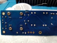
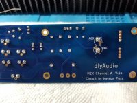
SO, decided that I would plug in one of the new boards just completed. These have been triple checked for accuracy and clean soldering and there are no problems. See the attached photos.
Got all back assembled and checked carefully the linear voltage coming in. It is at +/- 25.88 dc volts, what the Universal Power Supply generates.
Started all up with the 2 to 4 wiring suggested by MJ above and everything looked OK for about 3 minutes then some small amount of smoke appeared in the new board on the large cap side -- that is almost certainly done correctly.
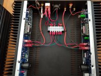
Perhaps the wiring I am using in the unit is, somehow, at fault. The + and - feeds go to a kill switch, then splitter, and the shared negative goes directly to the splitter. After splitting, the feeds go to the two boards and have been measured at, exactly, the PSU output: 25.88 vdc. See the attached photo. The left-side RCA is shown being shorted out -- this does not appear to make any difference as have tried it both ways and the smoke always appears.
It seems as if there is some problem with the left side of the unit but it has been carefully checked and it is exactly the same as the right side of the chassis--that has always worked fine. The middle pins of the mosfets have always been checked against ground and they never have had continuity.
Don't know how to proceed any more -- have spent countless hours on this project and the trouble channel/chassis side just will not clear up.
Any suggestions will be appreciated but think that there is some mystery here that might elude us all. One idea might be that the PSU is generating too much power, but this never happens with the right channel.
Got the transformers yesterday and plugged one into the original trouble card that had been completely redone with new diodes, caps, 8 resistors (others checked OK), transistors, and mosfets. Started to smoke after about 3 minutes in the area over .47R on the transformer side. Checked carefully all of the soldering and such and all was fine. Decided that it was likely the board itself had been damaged during the transformer blowout as there is some black internal spotting that might indicate harm.
SO, decided that I would plug in one of the new boards just completed. These have been triple checked for accuracy and clean soldering and there are no problems. See the attached photos.
Got all back assembled and checked carefully the linear voltage coming in. It is at +/- 25.88 dc volts, what the Universal Power Supply generates.
Started all up with the 2 to 4 wiring suggested by MJ above and everything looked OK for about 3 minutes then some small amount of smoke appeared in the new board on the large cap side -- that is almost certainly done correctly.
Perhaps the wiring I am using in the unit is, somehow, at fault. The + and - feeds go to a kill switch, then splitter, and the shared negative goes directly to the splitter. After splitting, the feeds go to the two boards and have been measured at, exactly, the PSU output: 25.88 vdc. See the attached photo. The left-side RCA is shown being shorted out -- this does not appear to make any difference as have tried it both ways and the smoke always appears.
It seems as if there is some problem with the left side of the unit but it has been carefully checked and it is exactly the same as the right side of the chassis--that has always worked fine. The middle pins of the mosfets have always been checked against ground and they never have had continuity.
Don't know how to proceed any more -- have spent countless hours on this project and the trouble channel/chassis side just will not clear up.
Any suggestions will be appreciated but think that there is some mystery here that might elude us all. One idea might be that the PSU is generating too much power, but this never happens with the right channel.
Attachments
Last edited:
One additional curiosity. With no power supply input (completely removed), the speaker leads register +1.375 vdc. Both channels. Once the power is supplied, the correct reading around -0.05 from the leads (with RCA shorted) takes place. Not sure whether my meter is supplying this voltage but cannot figure why it would appear.
- Completely unplug amplifier from AC mains, from signal source(s), and from loudspeakers
- Short LeftSpkrPlus to LeftSpkrMinus using 16AWG test lead with banana jacks on both ends
- At the same time, also short RightSpkrPlus to RightSpkrMinus using 16AWG test lead with banana jacks on both ends
- Leave shorting wires installed for 60 minutes
- Unplug Left shorting lead and attach voltmeter to speaker output posts using alligator clips. Measure voltage and write measured value in lab notebook, immediately upon removing shorting lead
- Measure voltage again after 5, 10, 20, 40 minutes. Record measured values in lab notebook.
- Repeat above two steps for Right shorting lead.
Results are in.
2:45pm MST shorting begins
3:45pm 1 Hour and L=0.283vdc, R=0.284vdc
3:50pm 5-minute interval and L=0.423vdc, R=0.386vdc
3:55pm 10-minute interval and L=0.458vdc, R=0.420vdc
4:05pm 20-minute interval and L=0.493vdc, R=0.453vdc
4:25pm 40-minute interval and L=0.528, R=0.487
So, L recovered more quickly in the first 5 minutes but then the two channels progressed at the same rate. L is the trouble channel and R is the channel that has always worked.
Please let me know what, if anything, this means.
Thanks again.

- Home
- Amplifiers
- Pass Labs
- The diyAudio First Watt M2x