Ok, let's think of this another way. R6+RV1 is a variable resistor that has a minimum value (set by R6) and a maximum value. (set by the value of the pot)
If you use the "blasphemous heresy" values (which is the funniest name ever for something that adds flexibility with absolutely zero downside) You'll have a range of adjustment from 37K to 57K, or a delta of 20,000 ohms.
Do you think the 400ohms of 37.4K vs. 37.0K will make any operational difference?
No worries. 🙂
The amplifier circuit doesn't care what the value of that resistor is, it will work regardless. What it does (by adjusting the value of said resistor, I.E., turning the potentiometer) is centers the output stage in regards to ground, which we think of as "DC offset".
The amplifier circuit doesn't care what the value of that resistor is, it will work regardless. What it does (by adjusting the value of said resistor, I.E., turning the potentiometer) is centers the output stage in regards to ground, which we think of as "DC offset".
He was trying to get you to think Chip. I knew where he was going, probably a bunch of us, did not respond during a teaching moment.
If you read page one, you can figure this out as they speak of ways to work with an neg offset on some boards/builds.
6 never misses an opportunity to try and get people to figure it out on their own. If someone always just gives you a value and you no not why, you have learned nothing.
I find myself in the same boat as you much of the time, but I do try and figure it out, on my own, if I can.
I'm in the process of building an M2x. Since this is my first serious DIY project, I try to get the amplifier up and running slowly, step by step. I have built and checked Mountain View and Ischikawa cards. I will have the power supply ready in a moment. I want to make sure I can run and check the amplifier boards without daughter cards?

If you do all three of these actions before powering up an M2x amp channel card
then you won't force destructive amounts of DC into the Edcor transformer's primary coils.
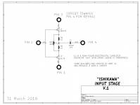
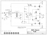
I strongly recommend that you use your DVM, in "continuity tester" mode, to become absolutely convinced that you've correctly identified bolt 2 and bolt 4. Studying the schematic of the amp card (mother board) below, you can see that only one of the four bolts has electrical continuity to capacitor C0. Eureka and congratulations, you have found bolt #2! Now devise a similar plan to identify bolt #4.
_
- completely remove the input stage daughter card
- short the IPS daughter card input (bolt #2) to the IPS daughter card output (bolt #4) with many figure-eight wraps of copper wire
- insert a shorting plug into the RCA input jack, which connects INPUTSIGNAL to GROUND
then you won't force destructive amounts of DC into the Edcor transformer's primary coils.
I strongly recommend that you use your DVM, in "continuity tester" mode, to become absolutely convinced that you've correctly identified bolt 2 and bolt 4. Studying the schematic of the amp card (mother board) below, you can see that only one of the four bolts has electrical continuity to capacitor C0. Eureka and congratulations, you have found bolt #2! Now devise a similar plan to identify bolt #4.
_
Attachments
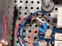
What Mark said, one more thing... I like the neat wires running under the grid, but I strongly caution you to remove then drill larger holes, deburr and install grommets.
Those holes are sharp and could easily cause a short. Please do something with those.
JT
Those holes are sharp and could easily cause a short. Please do something with those.
JT
I thought it was a bit dangerous and that's why I added extra insulation at these points. I have to correct this. Thanks.What Mark said, one more thing... I like the neat wires running under the grid, but I strongly caution you to remove then drill larger holes, deburr and install grommets.
Those holes are sharp and could easily cause a short. Please do something with those.
JT

Here's how I did it and the parts from Amazon:
https://www.amazon.com/Cal-Hawk-AZG...NW9&pd_rd_i=B002X4AFL0&ref_=pd_bap_d_rp_1_1_t
https://www.amazon.com/Cal-Hawk-AZG...NW9&pd_rd_i=B002X4AFL0&ref_=pd_bap_d_rp_1_1_t
Attachments
Last edited:
Just noticed..I'm starting to fill my first M2x amp board
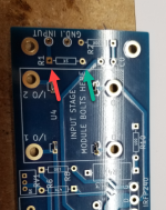
All of the resistors have a square at one end and a typical circle at the other end as shown on the circuit board photo.
Resistors are not polarized.
Why are these resistor holes showing squares and circles?
Thanks
All of the resistors have a square at one end and a typical circle at the other end as shown on the circuit board photo.
Resistors are not polarized.
Why are these resistor holes showing squares and circles?
Thanks
I am the person who laid out all seven of the PCBs that are in the package sold by the diyAudio store. Five input stage daughter cards, plus two amp channel boards which are (partial) mirror images.
I also laid out the other two input stage daughter card PCBs for the M2x, which the diyAudio Store does NOT sell. Instead, the PCB CAD files (in "Gerber" format) are freely downloadable by anyone. See post #3408 in this thread.
I also laid out the other two input stage daughter card PCBs for the M2x, which the diyAudio Store does NOT sell. Instead, the PCB CAD files (in "Gerber" format) are freely downloadable by anyone. See post #3408 in this thread.
If you do all three of these actions before powering up an M2x amp channel card
- completely remove the input stage daughter card
- short the IPS daughter card input (bolt #2) to the IPS daughter card output (bolt #4) with many figure-eight wraps of copper wire
- insert a shorting plug into the RCA input jack, which connects INPUTSIGNAL to GROUND
then you won't force destructive amounts of DC into the Edcor transformer's primary coils.
I strongly recommend that you use your DVM, in "continuity tester" mode, to become absolutely convinced that you've correctly identified bolt 2 and bolt 4. Studying the schematic of the amp card (mother board) below, you can see that only one of the four bolts has electrical continuity to capacitor C0. Eureka and congratulations, you have found bolt #2! Now devise a similar plan to identify bolt #4.
_
All the pins on the PCB are described very well but of course( following your advice) I will check this description using DVM 😉
Thanks 🙂
All of the resistors have a square at one end and a typical circle at the other end as shown on the circuit board photo.
Resistors are not polarized.
Why are these resistor holes showing squares and circles?
Thanks
My photo didn't upload the first time.
Attachments
Help with a part
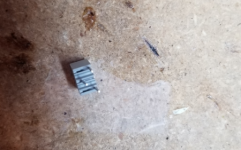
I ordered trimpot #858-64WR5KLF from Mouser and received units that don't have the three pins in a straight line. See photos.
Looking closer at the image at Mouser, I received what they offered.
I've searched the Internet with no luck in finding pins in a straight line with this product code.
I'm sure I'm missing something really simple, but would appreciate help in seeing where I'm confused.
thanks
Attachments
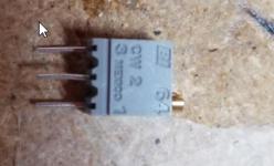
Chiptech, can you bend the middle leg enough for it to fit the PCB?
For a trimmer in the same series as what you already have, but with three
pins in a row, you can try 64YR5KLF:
https://www.mouser.ca/ProductDetail...ctronics/64YR5KLF?qs=z4G76Bmj19TgDS/A2tsaFg==
You can see the pin arrangement in the datasheet. For example, on page 3:
https://www.mouser.ca/datasheet/2/414/64-1528379.pdf
One more part..
I'm confused by the part for CB3: #505-MKS41.0/100/10 from Mouser is 100V 1.0uF instead of 1uF, 50V as indicated on the BOM. Will that work or do I need a new part #?
Thanks again
I'm confused by the part for CB3: #505-MKS41.0/100/10 from Mouser is 100V 1.0uF instead of 1uF, 50V as indicated on the BOM. Will that work or do I need a new part #?
Thanks again
Chiptech, can you bend the middle leg enough for it to fit the PCB?
For a trimmer in the same series as what you already have, but with three
pins in a row, you can try 64YR5KLF:
https://www.mouser.ca/ProductDetail...ctronics/64YR5KLF?qs=z4G76Bmj19TgDS/A2tsaFg==
You can see the pin arrangement in the datasheet. For example, on page 3:
https://www.mouser.ca/datasheet/2/414/64-1528379.pdf
I believe I can. I can just see the middle pin thru the hole on the solder side.
- Home
- Amplifiers
- Pass Labs
- The diyAudio First Watt M2x