LED doesn't work
I have built my PSU, the exact same as I use in my F5.
It passed the dim bulb test.
It test out around 24 V for both V+ and V-.
But one of the LED's doesn't work.
So I replaced, making sure polarity was correct the first time and second time.
Turned it back on and the same side LED doesn't work.
Any thoughts? Bad lot of LEDs? i have seven left. I'm using NTE #NTE3186.
Thanks.
Attachments

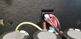
Are you sure about the LED polarity, Chiptech? On the V- side of the PSU, positive LED leg should be towards the Ground.
Powering up m2x without buffer and offset won’t settle, first going up to couple of volt intill mosfets gets biased then under a few minutes going back to -400mV. RV1 seems to have no effect. Any ideas how to fix offset?
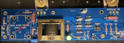
Harris at Q2
Bias steady at 1.3A
Harris at Q2
Bias steady at 1.3A
Are you sure about the LED polarity, Chiptech? On the V- side of the PSU, positive LED leg should be towards the Ground.
I did not know that. Thanks. I will reverse it.
Powering up m2x without buffer and offset won’t settle, first going up to couple of volt intill mosfets gets biased then under a few minutes going back to -400mV. RV1 seems to have no effect. Any ideas how to fix offset?
Harris at Q2
Bias steady at 1.3A
3. WARNING: BLASPHEMOUS HERESY! DO NOT READ THIS! Some DIY builders of the M2 amplifier, using the very fine “Tea‐Bag” circuit board, have reported a problem to the diyAudio forums. Their M2 amplifier’s output offset voltage is negative, and no setting of trimmer resistor RV1 removes this negative offset. I would like to gently mention a possible fix: leave R7=47K, but change R6 to 37K and change RV1 to 20K. Now (R6+RV1) can vary from 37K to 57K, in other words, from (10K less than R7) to (10K more than R7). This lets you null out either polarity of offset voltage. However, to faithfully reproduce Nelson Pass’s original M2 design, the M2X schematic and PCB silkscreen do not include this modification. M2X has R6=47K and RV1=5K. If you decide to make this R6,RV1 modification on your M2X, don’t tell anyone. And don’t quote me.
(Editor's note - (Jim) In my experience with all these Pass projects, I've found that Papa's coffee cans full of parts are really well sorted and all seem to be "center of tolerance " parts. This means that when we buy parts in low quantities we end up with parts that are further along the curve, so to speak... and need to have a bit more adjustment around them to set biases and null offsets and the like. The BA-3 Complimentary has needed this as well as the Tea-Bag M2 board, and the M2x. Anyway, my point is to agree with Mark and strongly suggest making the changes to that resistor and pot; all it does is give more adjustment to center the operating points, and because we can use our parts and properly adjust the circuit, it will sound better. )
Per Mark Johnson on page 1, post 3. l I highly suggest you read that and the posts around it... good tips there and can answer many questions.
Last edited:
Yes, I followed the blasphemous heresy but still. Same on both channels. Pot do no effect. Time to replace the pots. Tried with bigger R7 with little less off.
R6: 38k
37: 52k
RV1: 20k
R6: 38k
37: 52k
RV1: 20k
Are you sure about the LED polarity, Chiptech? On the V- side of the PSU, positive LED leg should be towards the Ground.
Well changing polarity worked. I must have just had made a mistake on my first PSU, so I lucked out.
Now I know what to do.
Thanks very much.
Yes, I followed the blasphemous heresy but still. Same on both channels. Pot do no effect. Time to replace the pots. Tried with bigger R7 with little less off.
R6: 38k
37: 52k
RV1: 20k
What are your rail voltages?
Are they symmetrical?
If you use blue Bourns pots then the chance that they are defective on both channels is not very high? .....you can measure them?
I’m using a desktop psu with +-23.5 for test. I will use my dual psu that worked splendid on other amps. I have built Tea-bags M2 with no fuzz. The difference this time is without buffer, bypassing I/O2-I/O4.
I’ll try to do some measurements after coffee.
I’ll try to do some measurements after coffee.
Q2 should be a Negative and those two values Q1 & Q2 should be very close, I've built 3 of these and never seen a 30mV diff between Q1-Q2
I have one open rolling cards and the +5.125 -5.112
You didn't include the source voltages... I bet the one is off too.
I have one open rolling cards and the +5.125 -5.112
You didn't include the source voltages... I bet the one is off too.
Last edited:
Starting my M2x amp build. I'm puzzled that I can't seem to find a 37K resistor to save my life online. Or I can buy a 1000 of them as a minimum. What is so special about 37K?
Can I substitute 37.4K?
thanks
Can I substitute 37.4K?
thanks
Do you plan to install it in series with a variable resistor, specifically a multi-turn trimmer potentiometer?
Sorry, was totally unclear.
I'm swapping out the 47K to 37K on the R6 to null out the offset voltage.
Per #3.
thanks.
I'm swapping out the 47K to 37K on the R6 to null out the offset voltage.
Per #3.
thanks.
...That resistor (R6) is in series with a variable resistor. (RV1)
Do you think the precise value is required? 🙂
Do you think the precise value is required? 🙂
- Home
- Amplifiers
- Pass Labs
- The diyAudio First Watt M2x