Pass DIY Addict
Joined 2000
Paid Member
Kevin: sum the output of ch1 and ch2 from your bench supply. This gives you about 65w per channel, which is right on target for one channel. To calc temp, take power dissipation (65w) and multiply it by the c/w rating of your sink for that channel. This will give you ballpark expected temp rise over ambient. For example, 65w dissipation multiplied by a sink with 0.40 c/w rating will yield an approx temp rise of 26c above ambient. This is about right, you want to target a maximum of a 25c rise over ambient. A bigger sink (smaller c/w number) will provide better cooling with a lower temp rise.
Last edited:
The attached chart which lists the thermal resistance for different sized heatsinks is useful. Both my calculations and measurements are in sync with the data listed for a Dissipante 4U/300 to which the M2X is attached (that makes it fun!).
What I don't understand about this chart is how the Max Power Dissipation increases so drastically as you add devices.
What I don't understand about this chart is how the Max Power Dissipation increases so drastically as you add devices.
Attachments
Pass DIY Addict
Joined 2000
Paid Member
I'm not sure that I understand the calculations and/or usage conditions that lead to those last three columns either 😕
The 4U/300mm deep chassis has two sinks that are each rated at 0.31c/w. If each channel of your M2X burns off 65w of heat, you are looking at a thermal rise of about 20c over ambient for each sink. This is a good temp for a slightly cooler running amp.
I'm using their 3U/300 cabinet for my Sony VFet2 (also ~65w per channel) and I'm getting about 25cc rise over ambient - just as expected with the calculations.
It makes sense that the max power dissipation would increase when more output devices are used. Improved thermal conductance from increased surface area. So, for example, an F4 could be run at higher power than an M2, using the same size heatsinks.
Am following along with these calculations and, am also running the right (working) channel of my M2x in a 2U chassis for an hour to check the DC offset. The DC value is switching between a low of -0.05 to sudden shifts to -0.135 or so at the lowest setting of the trimpot. Mostly stays around -0.055. NOW as regards temperature, the heat sink is moderately hot (not warm). You can touch it but not for very long. Don't have the thermometer until tomorrow and will check it then.
Have read the page one considerations of resistor value changes to alter this DC value and am unsure as to whether -0.055 is "good enough." Any comments will be appreciated.
Have read the page one considerations of resistor value changes to alter this DC value and am unsure as to whether -0.055 is "good enough." Any comments will be appreciated.
Pass DIY Addict
Joined 2000
Paid Member
I would not worry about 55mV of offset. This is very small. In addition, as you’ve noted, this will move around over time. It will be different in summer than it is in winter because of different ambient temperatures in your house. It will never be “perfect.”
As for temperatures, Nelson posted this years ago and it is still valid:
Blimey Hot : 10 seconds hands on = 45c
Crikey Hot : 5 seconds hands on = 50c
Bloody Hot : 2 seconds hands on = 55c
X*?@! = 60c
Read your temperature accordingly…. Generally, north of 50-55c means you should be looking for larger sinks.
Eric: Thanks. Will have the parts from Mouser tomorrow to rebuild the trouble channel and can make more tests then. The 2U chassis is certainly not "Blimey Hot." (Love the phrase). Held my hands on the sinks for 20+ seconds and could have gone on longer. But, also, will have the thermometer tomorrow and can make actual measurements.
BTW, have several AC Infinity fans lying around ready for use. These get used with my Emotiva XPA-1s that can easily reach 160 degrees (know because if they are off and the monoblock runs, when turned back on, that is the temp registered).
Ran this by the engineers at Emotiva many moons ago and one of them suggested that the smaller XPA-1L sounded best at 150 degrees. But, then, some others laughed and chimed in that they may sound the best at this temp, but will not last the longest.
Using the AC Infinity, you can dial in the temp you want maintained and I use 95 degrees for the Emotivas. This feels warm to the touch of the heatsinks but not overly so.
BTW, just an off-topic question. Have been poring over the backordered main board parts to see if any become available and am wondering about the alternate I selected for CB3. This is a non-polar cap, right? There are square indications of polarity on the board itself but I am assuming a non-polar cap is correct.
Yes CB3 is basically a non-polar bypass of the larger electrolytic. Film, preferably polypropylene or polycarbonate.
Pass DIY Addict
Joined 2000
Paid Member
…suggested that the smaller XPA-1L sounded best at 150 degrees. But, then, some others laughed and chimed in that they may sound the best at this temp, but will not last the longest.
Nelson made some comment a while ago to the effect of: output mosfets sound better with increasing bias current, right up to the point where the catch fire.
So, it seems that you have several experienced engineers that agree with one another!
OK, got some actual temp figures -- the thermometer arrived today and I have checked the M2X right, working channel after 15, 30 and 45 minutes. Starts out around 45 degrees at 15, then shifts up to 52-58 at 30 (depending upon where you measure) and then stays there at 51-57 after 45.
Now, I keep my new dual smps ACA on all day and checked its heatsinks. Uniformly 58 on the right and 59 on the left. Has felt slightly hot to me in the past but not overly so.
NOW, once again, PaulInWA recommended this Helect Infrared thermometer ($20 on Amazon) and it is superb -- thanks again, Sir Paul. Believe it was you that stated above that the 2U heatsink would be marginal and the figures above suggest this is so. BUT it is interesting that it is slightly less hot than the ACA.
Will continue to measure when both channels are operating. The Mosfets themselves are registering no hotter than the heatsink, but am not sure I am catching them at their hottest point.
Pass DIY Addict
Joined 2000
Paid Member
Simply raising those sinks a bit might result in lower temps. Give that ACA some legs, or something else, that lifts it off the desk so the bottom of the sinks have 1-2" of space under them. This will improve air flow and likely lower your temps by a few degrees.
Eric: Excellent advice. Have some spring speaker supports that will be ideal. Heard for some time that a Class A amp will get less hot during use and never knew whether this was true. Measured the dual smps ACA after an hour of play and found that this unit became one degree warmer -- 59 and 60 degrees. So no longer sure about that old adage.
Perspective: the figures supplied above for my Emotiva amps are, of course, Fahrenheit. If you take the 150 degrees and translate them to celsius that's about 65. And my ACA seems to sound ideal close to that mark -- 59-60.
Using AC Infinity fans, keep the large XPA-1s at 95 Fahrenheit which is 35 celsius. This was done in consultation with Emotiva in order to promote longevity. Will try raising that up to 55 celsius to see if the amp sounds markedly better at 131 degrees Fahrenheit.
If you are building your own amps, you can sacrifice longevity for sound quality as long as you know what to replace.
The general principle is correct – diverting current from flowing through the output devices to your speakers instead does reduce the output device dissipation. However.. unless you are running your Class A amp at full steam, it is unlikely that you will notice a drop in heatsink temps.
More smoke Woes...Woe is Me...
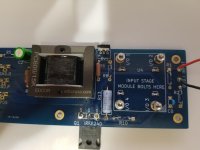
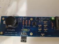
Got the parts today and rebuilt the entire section over the misplaced mosfet IRFP9240 where the smoke had first appeared and 3 resistors were fried. Replaced the 4 resistors and the 3 transformers nearby and checked the diodes -- they are all OK. Then reassembled and started the amp. Worked OK for a minute or two, then smoke started (again!) coming out of the other side of the board -- from the upper left of the daughterboard. The .47R 3 watt resistor was also stressed at this time. Replaced that resistor and tried it with no daughterboard. Made no smoke. Then put a different daughterboard in (Tucson) and started it up and, again, smoke started. Stopped, took Tucson out, and checked to see if it would run OK without any DB. It did. So, checked it with a speaker to see if any sound would come out. Nothing. No sound at all.
So, when you add the daughterboard, it starts smoking. Does this indicate the transformer has been blown?
Am getting frustrated with this trouble board and think you have to start over with a completely new main board when the mosfets were switched initially.
Any suggestion would be appreciated.
Time to go for a walk, I think (LOL).
Might need some pictures, to assist. You don’t mention it, so you should take a step back and build a dim bulb tester (DBT) and always use it when powering any amp for the first time. It will let you “see” if there is a problem and pulling excessive current before it damages things.
Got it and it's on the to-do list. But this was not a first-time turn-on.
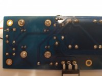
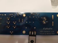
Do not think that photos will help -- the board looks just like it did in the photos above except the mosfets have been replaced and switched to the right places and resistors and diodes have been all either replaced or checked for accuracy.
What would cause daughterboards to be distressed and start smoking once they are added to the main board is the remaining problem and the choices are 1) the Edcor transformer, or 2) any of the capacitors. Can check the capacitors after removal but not sure about how to check transformers.
If anyone want a specific picture of some section of the board, just ask and it will be supplied.
- Home
- Amplifiers
- Pass Labs
- The diyAudio First Watt M2x