Was wondering about the potential advantages of discrete power transformers for each channel and, as you know, have been building the ACAs with a dedicated smps for each -- seems to work great but have no comparison -- unlike Zamjazz27 who reports they are superior.
Am adding rhthatcher's CLC power filters to both of my ACAs and will note their effect on your thread. Hoping that my initial linear power supply can be augmented as my knowledge and ability increase. This one is very simple with very powerful components recommended by you and PaulInWA.
Am adding rhthatcher's CLC power filters to both of my ACAs and will note their effect on your thread. Hoping that my initial linear power supply can be augmented as my knowledge and ability increase. This one is very simple with very powerful components recommended by you and PaulInWA.
... solid copper ...
... crimp ... .
Craigl59, I can only strongly second 6L6's request to only use stranded wire for an umbilical. I understand that you have ordered stranded, silicon-sheathed wire for the umbilical now, but I feel the need to emphasize this point for the benefit of others reading this thread and thinking about solid wire.
- In most countries' electrical codes, solid wire is only permitted for fixed installations. If cables are moved around, solid wire will break sooner or later.
- You can't securely crimp solid wire. It will not give a reliable connection in the first place, and loosen with movement. NASA forbids this in the work done for it as well: CRIMPED TERMINATIONS GENERAL REQUIREMENTS
Regards,
Claas
chede: Duly noted...however...my initial question was, simply, to find out the amp draw of the M2X boards. Earlier in this thread it is reported as 1.3amps, apparently a constant draw. The remaining issue that I cannot find addressed on the web is what ampacity does a certain gauge of stranded copper wire have? Know this for solid wire but do not know it for stranded wire and this spec is not given by any of the vendors I have ordered from.
AGAIN, assumed above that stranded wire might be variable here because of the number of strands AND that it will be less than solid. But I have found no hard data on the Internet.
To come back to your emphasis: yes, you should use stranded wire for safety and reliability reasons. But what ampacity will be provided by the 18awg cable ordered above? Don't know.
Have a look at Wikipedia,
American wire gauge - Wikipedia -
there is a section "Stranded wire AWG sizes". In the first paragraph, it is stated that in the AWG system, only the actual copper cross-section is counted, making a stranded wire of a certain AWG larger in diameter than a solid wire of the same AWG.
From that follows that the "Ampacity" of stranded wire with AWG x is the same as that of solid wire with AWG x.
Hope that helps,
best regards, Claas
Solid and stranded wires do not carry the same ampacity:
"As electrical currents pass through wires, a skin effect occurs. That part of the current closest to the outer layer of the wire, the ‘skin’ area, is where electricity travels along the outside surface and is subjected to magnetic fields, tends to dissipate into the air. Power dissipation is an ever-present challenge for electricians & engineers. Because of its thickness, solid wire has a decreased surface area that reduces dissipation. Because of the given thickness of stranded wire, i.e., it’s thinner, there are more air gaps and a greater surface area in the individual strands of wire. Therefore, it carries less current than similar solid wires can."
FROM: Stranded Wire vs Solid Wire in Electrical Applications
Numerous other sources on the web state this and your Wikipedia source does not say the two carry the same amperage.
For the 4th time: do not know what ampacity an 18 AWG stranded wire has but the solid wire will pass 16 amps for chassis wiring and 2.3 amps for power transmission.
Last edited:
Hi, if you look at post #1 in this thread you'll see who wrote it: me. I built my own personal M2x using (this particular wire). It worked very well for me.
This page has the wire gauge chart that i use:
American Wire Gauge Chart and AWG Electrical Current Load Limits table with ampacities, wire sizes, skin depth frequencies and wire breaking strength
For chassis wiring, 18 ga can carry 16 Amps.
American Wire Gauge Chart and AWG Electrical Current Load Limits table with ampacities, wire sizes, skin depth frequencies and wire breaking strength
For chassis wiring, 18 ga can carry 16 Amps.
Solid and stranded wires do not carry the same ampacity:
"As electrical currents pass through wires, a skin effect occurs. That part of the current closest to the outer layer of the wire, the ‘skin’ area, is where electricity travels along the outside surface and is subjected to magnetic fields, tends to dissipate into the air. Power dissipation is an ever-present challenge for electricians & engineers. Because of its thickness, solid wire has a decreased surface area that reduces dissipation. Because of the given thickness of stranded wire, i.e., it’s thinner, there are more air gaps and a greater surface area in the individual strands of wire. Therefore, it carries less current than similar solid wires can."
FROM: Stranded Wire vs Solid Wire in Electrical Applications
Numerous other sources on the web state this and your Wikipedia source does not say the two carry the same amperage.
For the 4th time: do not know what ampacity an 18 AWG stranded wire has but the solid wire will pass 16 amps for chassis wiring and 2.3 amps for power transmission.
the skin effect is mostly applicable to RF, not so much AF (it is frequency dependent).
using thin wire will fix most issues when AF is involved.
there are a few calculators found online that one can use if this is a concern.
when DC is concerned skin effect is not a problem even with very thick wire, so no reason really to use solid wire for power runs (flexibility is probably more important factor here plus current carrying capacity)
Last edited:
Been listening on 2 records with the Cederburg now.
And its VERY detailed,wide sound stage and solid ground.
Yeah I like it,will listen a day or two and then change IPS....
And its VERY detailed,wide sound stage and solid ground.
Yeah I like it,will listen a day or two and then change IPS....
Distressing news...
Got the PSU done with Paul's help and it works fine. Just finished the M2x and got it all setup for the initial calibration. Checked with posts above and Paul and shorted out the left channel RCA, attached the voltmeter to the speaker inputs, and turned on the PSU.
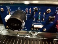
Smoke from the front of this left channel board, from the resistor area R9, 12, and 11. Turned everything off and checked the board -- Paul was kind enough to call with assistance. Saw that the resistor R12 was burned almost in half and when checked, registered 34 ohms.
Hooked the M2x back up and (without RCA shorting) checked the other channel. It works fine. Then plugged the damaged channel in as well and it makes music but with a lot of background hiss and static.
Had a 100 ohm resistor around and replaced R12. Made no difference. There is a small black/burned spot under R11 but do not have a 221 ohm resistor lying about.
Q5, Q6, and Q7 attach to these resistors and Q6 got bent slightly askew during construction -- it might be damaged. The mosfets are in their correct position, triple checked.
So, the trouble channel tries to make music but clearly has some damage. Will start replacing the various components around these 3 resistors and would appreciate advice from the knowledgeable pundits onboard.
Paul noted that the Vishay/Dale resistors I ordered were the very small blue ones and might be a problem. Ordered 1/4 watt resistors as best as possible and do not know if another wattage or type would be ideal.
And thanks for your help. Got 2 ACAs built trouble free, one linear PSU (works great), and half of a M2x. Now to see if I can get the other half...(LOL).
Thanks, people.
Got the PSU done with Paul's help and it works fine. Just finished the M2x and got it all setup for the initial calibration. Checked with posts above and Paul and shorted out the left channel RCA, attached the voltmeter to the speaker inputs, and turned on the PSU.
Smoke from the front of this left channel board, from the resistor area R9, 12, and 11. Turned everything off and checked the board -- Paul was kind enough to call with assistance. Saw that the resistor R12 was burned almost in half and when checked, registered 34 ohms.
Hooked the M2x back up and (without RCA shorting) checked the other channel. It works fine. Then plugged the damaged channel in as well and it makes music but with a lot of background hiss and static.
Had a 100 ohm resistor around and replaced R12. Made no difference. There is a small black/burned spot under R11 but do not have a 221 ohm resistor lying about.
Q5, Q6, and Q7 attach to these resistors and Q6 got bent slightly askew during construction -- it might be damaged. The mosfets are in their correct position, triple checked.
So, the trouble channel tries to make music but clearly has some damage. Will start replacing the various components around these 3 resistors and would appreciate advice from the knowledgeable pundits onboard.
Paul noted that the Vishay/Dale resistors I ordered were the very small blue ones and might be a problem. Ordered 1/4 watt resistors as best as possible and do not know if another wattage or type would be ideal.
And thanks for your help. Got 2 ACAs built trouble free, one linear PSU (works great), and half of a M2x. Now to see if I can get the other half...(LOL).
Thanks, people.
Attachments
Pass DIY Addict
Joined 2000
Paid Member
Check from the bottom to be sure that no leads from the bottom of the board are hitting your sink and causing a short. Did that on one of my ACA builds…
Edit: whats going on with that 9240? Looks like it is mounted ON the chassis rail. Be sure it is electrically isolated from the chassis.
Soldering on top leg of R12 also looks suspect. This should be reflowed with a bit more solder to completely fill the hole.
Edit: whats going on with that 9240? Looks like it is mounted ON the chassis rail. Be sure it is electrically isolated from the chassis.
Soldering on top leg of R12 also looks suspect. This should be reflowed with a bit more solder to completely fill the hole.
Last edited:
Yes, all of the transistors were carefully checked for orientation when assembled. Thanks for asking. The diodes are also correct in polarity and will check their values individually. Do not think they are the problem, however.
Again, both boards where assembled the same and the right channel works fine. This leads me to think that the problem must be either 1) the RCA shorting and testing process, or 2) the bent transistor Q6.
Am ordering replacement components for the entire section of the board and the mosfets as well just to be prepared. With the holiday delay, won't have them until late next week. Will offer even more desoldering practice, and I have learned the pleasures of a quality solder sucker.
Last edited:
Edit: whats going on with that 9240? Looks like it is mounted ON the chassis rail. Be sure it is electrically isolated from the chassis.
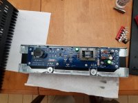
The close proximity of the mosfets to the support rail is the result of having ordered a 2U chassis from HiFi2000 using their published height specs -- that led me to believe the board and mosfet would fit. In fact, it is very tight. However, the washer is to ground as is the rail and the heatsink. So don't think that could be the cause. Have ordered replacements, anyway, and will hope they work.
Here is a pic of the initial heatsink/circuit board combination.
Attachments
Last edited:
Pass DIY Addict
Joined 2000
Paid Member
Ok, now I understand how the mosfets were mounted. That looks much better than I was imagining 😉
Pass DIY Addict
Joined 2000
Paid Member
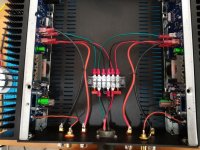
Is that a single strand of wire or a cat hair between terminals 4 and 5 on the top of your terminal block?
Eric: The rails had to be cut in order to make room for the mosfets. Upper rails needed massaging as well. Bottom line: order at least the 3U chassis for the M2X.
And if you need to drill and tap the holes in the heatsink, make sure you have a drill press and use plenty of WD40 during the tapping.
On the other hand, drilling the back panels for your specialty hardware needs is trivial -- both a drill press and Bosch jig saw go right through the 3mm aluminum.
And if you need to drill and tap the holes in the heatsink, make sure you have a drill press and use plenty of WD40 during the tapping.
On the other hand, drilling the back panels for your specialty hardware needs is trivial -- both a drill press and Bosch jig saw go right through the 3mm aluminum.
- Home
- Amplifiers
- Pass Labs
- The diyAudio First Watt M2x