IPS7 actually includes bootstrapped supply rails, a stunt which increases PSRR by at least 30 dB. So if you've chosen the OPA1611 opamp, whose PSRR at 120 Hz is 110dB all by itself with no bootstrapped rails (see red circle),
... putting that chip into an IPS7 board raises the PSRR to at least 140dB. Every volt of noise on the supply rails becomes 0.1 microvolt of noise at the input.
If you've set your volume control so your M2x is delivering 1 watt into 8 ohm speakers (sqrt(8) volts output, 0.47 volts input), supply noise + imperfect PSRR establishes a noise floor at -133dB. A little less than one part in (2 raised to the power 22).
Attachments

IPS7 will be my next input board project. I have put OPA134 in the RS-Component basket along with some other components. Today I will build a small low distortion 1 kHz oscillator for noise measurement. It uses a LME49720 this one:
https://docs.rs-online.com/1fed/A700000006723661.pdf
It looks as it could be interesting to try also.....don't know if is exists in a single opamp version also but IPS7 can take both types.
In the moment I evaluate IPS6 and my first impression is that it has very crystal clear "top end" and also good control in the "low end" so overall positive so far.
What I noticed is that compared to Norwood the "white noise" from tweeter with ear close to unit is louder when IPS6 is installed. Norwood is very silent. I assume IPS6 is unity gain also......if you can say this about a voltage controlled current amp which works into an inductive load. I notice that the output signal is coupled 100% back to the diff amp "other" input. This ensures "unity gain" at all frequencies (this is my assumption)?
The LME49720 seems to be named LME49710 in single op amp version. Then noise performance is slightly lower.
I have 3.4mV so problem is in crc filter board.Amp Board L => PSU R => You should get 0V across Audio Ground and Chassis Ground
LME49710 has been end of lifed. They may be hard to find.
Ok, then I may just use the dual amp version. Good the IPS7 is "flexible".
I also think my primary source only has it in smd version. But this can be solved using adapter boards.
The spec on this op amp looks good......but it does on most op amps.
I have 3.4mV so problem is in crc filter board.
That is very interesting. I admit that I am surprised.
So, it is isolated to the right side of the power supply. At least one step further, but not that much closer to a real answer for you. 🙁
There are other low noise interesting op amps to try out like:
https://docs.rs-online.com/0a2a/0900766b813852a5.pdf
and:
https://docs.rs-online.com/17a3/0900766b8077fea5.pdf
....I may put them into the "basket".....it will be fun to play with IPS7 boards.....
It seems "super" high end companies never uses op amps in the signal path?
Why? ....because it is not accepted by their costumers even if it was blind tested to sound better?
During recording etc......the "music" has probably "seen" many op amps....
I checked the Tucson card and it's just as quiet as Ishikawa. Will Norwood and Austin be quiet too? I understand that Mountain View will not play well until I replace the power supply?
Norwood is very quiet. The IPS7 board is a Tucson++ where the power supply part locally onboard has been enhanced compared to Tucson. If you go to top there is a link to where the IPS6 and 7 boards are explained in details.


Hi,
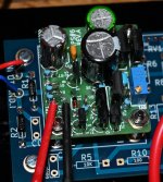
I cannot seem to tune my IPS6 boards. I am getting 5.12 Vdc at across TP1 and TP2 and does not move as I move RV1 CW and CCW up to what I thought the end of the range. One of the pic is showing R5 with a jumper, but I already cut the wire for both boards and R5 is now open.
Suggestions anyone? Thank you!
Abe
Last edited:
It seems you need to turn your 2 x J113 JFETs 180 degree....the "flat" side has to face in direction of the potentiometer. All of the small TO-92 transistors face same direction.
Hi,
I cannot seem to tune my IPS6 boards. I am getting 5.12 Vdc at across TP1 and TP2 and does not move as I move RV1 CW and CCW up to what I thought the end of the range. One of the pic is showing R5 with a jumper, but I already cut the wire for both boards and R5 is now open.
Suggestions anyone? Thank you!
Abe
Check and re-flow solder pads on the bottom of the little PCB, especially around RV1.
Will do!
Can I test the IPS6 by just applying VCC (+5V) on Pin 3 and Pin 1 to GND?
It seems you need to turn your 2 x J113 JFETs 180 degree....the "flat" side has to face in direction of the potentiometer. All of the small TO-92 transistors face same direction.
Thank you! I will replace them.
Abe
By "replace" you probably just mean "mount them correct"......as I assume you have spent some time on matching the JFETs?
By "replace" you probably just mean "mount them correct"......as I assume you have spent some time on matching the JFETs?
Yes, replace. I have 4 match JFETS (J113) that was given to me by gracious M2X owners here. I also have bipolar supply so I will test the boards before mounting them this time. Thank you so much!!
Abe
Last edited:
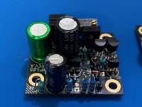
My IPS 6 still does not work. As soon as I mount it, theres a loud hum in both channels. I tried one channel at a time and hum is always present and I cannot see a change (0.07 mV on both channels) on TP1 and TP2 twirling RV1.
My IPS7 is quiet and works properly (installed in the amp at present).
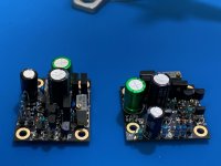
I already replace J113's as it was oriented wrong earlier. How do I check it outside of the amp? Please see photos and let me know what I missed. Thank you!
Abe
My IPS7 is quiet and works properly (installed in the amp at present).
I already replace J113's as it was oriented wrong earlier. How do I check it outside of the amp? Please see photos and let me know what I missed. Thank you!
Abe
Attachments
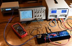
I built myself a input board "test bench" using a spare M2X amp board as picture shows and only mounted what necessary to test the boards. Works perfect.
Did you test the JFETs before inserting them into board....e.g. using one of the cheap component testers from China?
Maybe check all resistor values.....as it is easy to insert a wrong one....
Did you test the JFETs before inserting them into board....e.g. using one of the cheap component testers from China?
Maybe check all resistor values.....as it is easy to insert a wrong one....
Attachments
- Home
- Amplifiers
- Pass Labs
- The diyAudio First Watt M2x