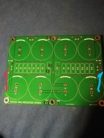
@darrr, I can confirm that my M2X was also picking a bit more noise with some cards than with the others. Mountain View gave it a bit more noise than Tucson or Norwood.
Noise induction
When using the Deluxe 4U chassis and the diyaudio store boards , the coil opening on the Edcor faces up. I have found , if the power transformer is mounted to the base plate instead of an L bracket then the noise pickup is minimized. Distance is also your friend.
When using the Deluxe 4U chassis and the diyaudio store boards , the coil opening on the Edcor faces up. I have found , if the power transformer is mounted to the base plate instead of an L bracket then the noise pickup is minimized. Distance is also your friend.
I got to the "what's next" point again and I am asking for help.
1. Something wrong with jfets if I have ~ 9mV DC at the output from Ishikawa?
2. What I hear is actually not noise, but a 100hz hum on Mountain View and the quieter 150/200 Hz from Ishikawa.
1. Something wrong with jfets if I have ~ 9mV DC at the output from Ishikawa?
2. What I hear is actually not noise, but a 100hz hum on Mountain View and the quieter 150/200 Hz from Ishikawa.
When you have output capacitor installed of Ishikawa there is no DC at output I assume?
There will always be a small amount of DC before output cap. You never get it to exactly 0V. It will depend of temperature of JFETs etc......
Try to disconnect power to one channel so power supply only have to drive other channel. Then the ripple noise should be reduced a bit and also if there is a ground loop issue this should disappear also......I guess. So also remove RCA interconnect from inactive channel.
@MEPER
DC output is only without C1. The question is, is 9mV not too much?
I don't have a ground loop. I don't have a PE (ground) wire in the installation, so I also do not have a PE connection to the chassis.
I have the inputs shorted with the Rca plugs, but as you suggest I will check each channel separately again.
Does the 5mV difference between the gnd with the left and right channel indicate a problem or it doesn't matter?
A few mV is to be expected unless you do a lot to ensure perfect balance.
As both channels are connected to same signal Gnd you should read 0mV between the two Gnd's....especially if you have shorted inputs. There should flow no current between the two signal Gnd's....so if you measure a voltage between them.....you also have a current....unless the impedance between the two signal Gnd's is infinite.....
As both channels are connected to same signal Gnd you should read 0mV between the two Gnd's....especially if you have shorted inputs. There should flow no current between the two signal Gnd's....so if you measure a voltage between them.....you also have a current....unless the impedance between the two signal Gnd's is infinite.....
Start to measure the impedance (set DMM to ohm) between to to Gnd points. Where do you measure? .....between Gnd at the two input RCA connectors?
It is best to have as close to 0 ohm as possible if they share the same power supply.
Even that each channel has its own capacitor from the common PSU board they share same signal Gnd?
Did you still have noise when only one channel was active (other channel not powered)?
It is best to have as close to 0 ohm as possible if they share the same power supply.
Even that each channel has its own capacitor from the common PSU board they share same signal Gnd?
Did you still have noise when only one channel was active (other channel not powered)?
Practically everywhere measured gnd I have 0.3 R but the shorted probes also show it to me, so I assume that it is 0R. The hum in Ischikawa is much quieter than in Mountain View. I can't hear the difference when one or two channels are on. Spectroid "sees" the differences - 150hz is dominant. I will also check Mountain View.
My crc filter I show here:
The diyAudio First Watt M2x
My crc filter I show here:
The diyAudio First Watt M2x
The pickup from Edcor will be 50 Hz so I think the 100/150/250 Hz noise is electrical coupled from power supply (not magnetic/capacitive coupled). The symmetric amp designs are good to reject ripple noise on a symmetrical PSU if there is even amount of ripple on each rail. If you have more ripple on one rail than the other then it could cause that more noise is introduced in the amp. But I am just guessing. You could check if you have even amount of ripple on both rails. If that it the case the "cure" may be to reduce ripple in PSU. You could try to build a PSU using two switch mode power supply adapters (two PC laptop adapters can do it) and your 150 Hz noise will probably be gone......just as an experiment.....
This is probably not the problem of the power supply, since Mountain View causes a 100hz hum. There is a little more noise from both channels . The pictures for comparison (phone about 3-5 cm from the speaker):
1-MV one channel
2- MV both channels
3 - Ishikawa one channel
What should I do to fix this?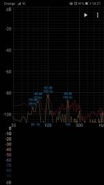
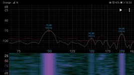
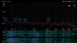
1-MV one channel
2- MV both channels
3 - Ishikawa one channel
What should I do to fix this?


The Ishikawa has a symmetrical design with a matched N and P channel JFET and is good at suppressing ripple noise on rails.
Mountain view seems to be not as good to handle this issue......and if I look at output stage Mountain view is not symmetrical. The 100 Hz noise is from PSU. So with the amount of ripple you have in current PSU you need good ripple rejection and Ishikawa is good at this and probably Tucson is also quite good.
Do you still think there is a problem if Ishikawa is used as input boards?
The only fix is to reduce noise in PSU......I have no better suggestion.....
Thanks MEPER
Ishikawa- I have to check the jfets that are mounted there. When I started the M2 clone I had pairs not so well matched and there was 3-4 mV at the edcor input. It should be better here, but it isn't. I have a spare, paired at Idss 9.6mA from fetaudio from HK.
What about the 5mV between the gnd of both amplifier boards?
It is not good to have voltage between Gnd at the two channels.
You almost had 0 ohm it seems between the points. Maybe you can measure where the 5mV occurs. Start with one probe at left channel Gnd and then with other probe start at right channel where you measure 5mV and then move this probe closer and closer on the "Gnd path" to left channel and see where you measure 0mV. Then maybe you can find a bad connection on the "Gnd path" that caused the voltage drop.
You almost had 0 ohm it seems between the points. Maybe you can measure where the 5mV occurs. Start with one probe at left channel Gnd and then with other probe start at right channel where you measure 5mV and then move this probe closer and closer on the "Gnd path" to left channel and see where you measure 0mV. Then maybe you can find a bad connection on the "Gnd path" that caused the voltage drop.
Following your advice, I checked the voltages and all points were 6mV. I thought about the chassis and found an interesting thing there.
As you will see in the schematic, gnd PS connects to the chassis through a thermistor. Here's what I measured:
Left 6.8mV to chassis
Right 0.8 mV to chassis
Can the thermistor be damaged? Or something else? One time something went wrong when I connecting the board and three resistors R1, 2 and 3 burned. I replaced them.What else might be damagedg- bleeder? caps?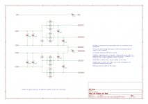
View attachment 903113
As you will see in the schematic, gnd PS connects to the chassis through a thermistor. Here's what I measured:
Left 6.8mV to chassis
Right 0.8 mV to chassis
Can the thermistor be damaged? Or something else? One time something went wrong when I connecting the board and three resistors R1, 2 and 3 burned. I replaced them.What else might be damagedg- bleeder? caps?

View attachment 903113
OK, so you measured signal Gnd to chassis?
I thought you measured left signal Gnd to right signal Gnd?
But you should measure exactly same values......signal to chassis....left and right. So you have a "resistance" somewhere in left channel.
I think a CL-60 is hard to damage.....you would see sign of that kind of damage. It probably measures about 10 ohm?
Yes. I measured gnd points between left and right channel. There is 6mV in each.
Yes. I measured gnd to chassis. And there are differences.
Yes. Termistor have 10r. I have 10r between chassis and both channels gnd.
Any hints what should I look for?
Yes. I measured gnd to chassis. And there are differences.
Yes. Termistor have 10r. I have 10r between chassis and both channels gnd.
Any hints what should I look for?
You can only find it by measurements.
If you measure voltage over CL-10 (signal gnd to chassis) you measure 0V?
Then you should start from there going the "Gnd-path" to left and right and measure gnd to chassis all possible places......until you have come all the way to RCA connector signal Gnd. Then you should suddenly measure a "difference" and you know the "error" is between the two last measurement points.......probably a bad connection.
You mentioned that the goal was to have a working amp before Christmas. The good thing is that Christmas has been cancelled this year.....so you have plenty of time.
- Home
- Amplifiers
- Pass Labs
- The diyAudio First Watt M2x
