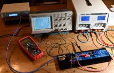
Here is one of the IPS#6 boards under test and adjustment.
250 kHz sine is not a problem and same with square wave. Scope trigges better on square wave than with Tucson when I magnify the rising edge. It is 100% stable.....but I don't know why. It is also just for fun I set the frequency to the generator max.
It consumes a lot more power than Tucson. -+24 V DC and 40 mA. It is about 2W and the large output transistors gets a little bit hot. Will see how stable I can get the 0V adjustment after 1/2 hour warm up or so. The final adjustment will be in amp. First IPS#6 seems to work as expected.
I made permanent test pints for the two test points. I use small hooks on the pins. Small good quality hooks are nice.
Attachments
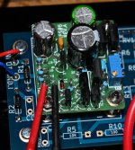
Regarding the temperature of the IPS#6 output transistors with -+24 VDC rails I used an IR gun and it showed just below 70 C where I got the max. reading.....so it is a little bit hot. What the junction temperature is....I should be able to calculate.....but I guess much below the max. temp it can handle.
The other IPS#6 board behaved exactly as the first one. 40 mA consumption at -+24 VDC and both boards are now adjusted and ready to go into the amps for final adjustment. The vertical position of the boards in the amp and that it is a closed box could change the working temperature a bit. I guess a few mV between the test points are ok.
I wonder if these boards are the most dedicated to drive the Edcor.
I wonder if these boards are the most dedicated to drive the Edcor.
CIRCUIT DESIGN OF IPS6
...
I thought it would be interesting to drive the Edcor transformer from a voltage controlled current source, namely a "transconductance" amplifier, instead. Perhaps the resulting sonics would be different and, I dared to hope, the differences would be pleasing. Readers blessed with excellent memory may recall that another example of a transconductance amplifier here in the Pass Labs forum, is the First Watt F5. John Curl's famous JC-2 linestage is also a transconductance amplifier.
In my opinion, any sonic signature that IPS6 + M2x might produce, is caused by driving the Edcor primary with a transconductance amplifier. A voltage controlled current source.
I liked the IPS6 circuit so well that I re-used its concept in the soon to be released "front end cards" for Nelson Pass's DIY VFET amplifiers. Nelson designed one front end card, we'll call it "almostIshikawa", and I designed four others which we'll call "S", "B", "M", and "D" ... from bottom to top in the photo below. Click on the image to remove foreshortening distortion, and then click on the white X at bottom left to see the image full size.
Card "D" at the top of the stack, shares a lot of DNA with M2x IPS6. They are both transconductance amplifiers, they both use the exact same KSA/KSC output transistors, and they both demand very accurate matching of bias currents in the input diffamp stage. The DIY VFET amp and all of its front end cards, ought to be released sometime before April Fools Day and perhaps even before Valentines Day. When they're finally out and when they're fully disclosed, put "D" side by side with "IPS6". I'm supremely confident you'll see a family resemblance.
Right now you can ask all the questions you want but the answers you get will be: ()
Patience is a virtue. In this case, patience is your only option.

But the new VFET amplifier.....we don't know much about......has no "interstage" transformer for the "gain stage"?.....so why is a front end with such a tremendous "drive" like an IPS#6 "alike" board needed in that specific amplifier?
I was just trying to elaborate what an IPS#6 "alike" board should drive in a VFET amp 🙂
......I mean the output transistors can drive a headphone like in 2018 line stage and on IPS#6 board they reach almost 70 C 🙂
......I mean the output transistors can drive a headphone like in 2018 line stage and on IPS#6 board they reach almost 70 C 🙂
But IPS#6 buffer has no voltage gain.......so voltage gain is probably in another place in that amp......unless it is an IPS#6++ .....with added gain stage....
Read Mark’s description of “D” again. He mentions that it shares a lot of DNA with #6.
Interestingly, humans and dogs have around 84% shared DNA. Understanding Genetics So that may not be a particularly good hint...
Interestingly, humans and dogs have around 84% shared DNA. Understanding Genetics So that may not be a particularly good hint...
Ok, I can see that VFET input boards are physical larger so it makes sense they have a voltage gain stage "on board"......
I bought my M2x set second-hand. Ischikawa and Mountain View were ready to run . I decided to remove C1 from the Ischikawa card and installed a jumper there. After checking the voltage at the output (pin4), I read 13.7 and 9.4 mV. I don't think those are the correct values. Should ~ 0mV be there?
I went back to Mountain View and ..... the 100hz noise (that I had been fighting from the beginning) came back. I don't know what could be the cause but I noticed there is a 5mV difference between gnd on the left and right channel . I don't know if this is normal ...
I have Ischikawa with C1 again. I can still hear the noise but definitely quieter and 100hz is no longer dominant. I have 0.5mV on pin4 (both channels) and still 5mV between L and R channel measured on gnd
Edcor noise null
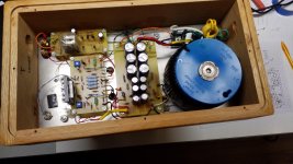
My Edcor transformers arrived today. I am retrofitting a pair F5 Mono-blocks I custom built years ago . My plan is to build a custom P.C.B. and do a board swap. I soldered the transformer to a test lead and hooked it to my oscilloscope . I then set it for maximum sensitivity. With the F5 powered up I moved the transformer around the chassis looking for minimum noise pickup. Minimum noise was found with both the toroidal and Edcor coil openings pointed in the same direction. The new board will have the transformer sitting on end.
My Edcor transformers arrived today. I am retrofitting a pair F5 Mono-blocks I custom built years ago . My plan is to build a custom P.C.B. and do a board swap. I soldered the transformer to a test lead and hooked it to my oscilloscope . I then set it for maximum sensitivity. With the F5 powered up I moved the transformer around the chassis looking for minimum noise pickup. Minimum noise was found with both the toroidal and Edcor coil openings pointed in the same direction. The new board will have the transformer sitting on end.
Attachments
- Home
- Amplifiers
- Pass Labs
- The diyAudio First Watt M2x