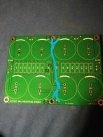
Ok.....so maybe it will be Chrismas this year also.....
Was it a bad solder connection or was caused the problem?
Was it a bad solder connection or was caused the problem?
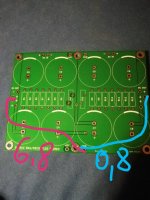
I found a difference in these places but not the cause. I don't know how to diagnose it.
I meant Christmas of course.
I meant Christmas of course.
Last edited:
But the two points has connection via the PCB ground plane?
It is a thick layer of copper.....so it must be a bad solder connection?
You should measure 0V between the two points which has the Gnd-symbol.
It is a thick layer of copper.....so it must be a bad solder connection?
You should measure 0V between the two points which has the Gnd-symbol.
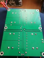
I would try to "re-flow" the solder joints on both side of PSU board and see what happens.....using a large solder tip and set solder iron to 450 C or so.....
It's a welder, I think ...😉 The laminate would be burnt through.
It is a fine old solder iron......good to keep heat at the tip. The large ground plane on your PCB will "suck" heat out of smaller irons....causing cold joints.
Then don't look further before you have 0V between the other two gnd-points.....
Then don't look further before you have 0V between the other two gnd-points.....
I improved the soldering at the gnd audio points. Next I did this:
1. I turned on the power supply without load - no difference and 0V between the chassis and the gnd
2. I turned on the power supply with only the left channel. Also 0V
3. I turned on the power supply with only the right channel. 3.4mV between chassis and gnd.
Will it help in the diagnosis?
Edit:
4 I turned on with both channels. No improvement, so 6.8mV on the right and 0.8mV on the left channel.
Last edited:
But between the two gnd-points.....20 cm from each other ......they are connected together via the PCB ground plane?
I can only thing about a bad connection.......
What is the voltage between the two gnd-points?
It must be zero......unless there is a very large current flowing between the two points...
What if you measure AC.....or is it AC voltage you measure?
I can only thing about a bad connection.......
What is the voltage between the two gnd-points?
It must be zero......unless there is a very large current flowing between the two points...
What if you measure AC.....or is it AC voltage you measure?
I would try to also re-flow the solder joints for the capacitors. There must be an "unbalance" somewhere. When charging these caps very high current is flowing and if one has a bad connection you will have much more current flowing in one part of the PCB which can maybe cause a difference in voltage between the two gnd-points.....
Yes, and I would say that it can only be caused by an uneven current flow and my guess is it could be a bad solder connection of caps, filter resistors etc.....some kind of "unbalance" between the two channels. Maybe connection to the bridges......
With power on but no load......you measure 0V?
So it seems the voltage difference is caused by a much higer current on side of PCB....is my best guess.
Maybe with load measure voltage over filter resistors on both channels using your scope to see if you can see a difference......also check resistor values and the solder connections.
Thanks to MEPER for so much time helping me. I will re-solder the filter PCB. Is it possible that the capacitor is damaged? How to check it without desoldering?
I would consider them as not damaged and just assume that you have a bad solder connection on the board.....somewhere.
If they charge up to expected voltage and then slowly de-charge when powered off they are probably ok.
If they charge up to expected voltage and then slowly de-charge when powered off they are probably ok.
Ok, but if you have 0 ohm between all the Gnd-points on PCB then regardless of which Gnd-point you measure from to chassis......it should measure the same. At least in theory. All Gnd-points on PCB are connected to each other via the PCB ground plane so you should not have any voltage drop in that ground-plane. Of course the world is not ideal....but here I think it should be "ideal enough".
Maybe try the DiyAudio Store universal PSU PCB next time 🙂
Maybe try the DiyAudio Store universal PSU PCB next time 🙂
I can only confirm. All audio gnd points on both amplifier boards are 0R (cheap meter shows 0.3R) All gnd audio points to the chassis are 10R. Maybe I will ask the designer in his thread.
There is also the question of the difference between the Ishikawa and Mountain View cards. Is it possible that the PSRR of the amplifier changes depending on the type of input card and the power filtering requirements increase?
There is also the question of the difference between the Ishikawa and Mountain View cards. Is it possible that the PSRR of the amplifier changes depending on the type of input card and the power filtering requirements increase?
Last edited:
Yes, the symmetrical input boards will usually have better PSRR and Ishikawa is one of those. Also the opamp based input boards should be good at this. The best opamp board is the new IPS#7 which has additional filtering for the power supply "on-board".
Looking at Mountain view......it does not look symmetrical.....but better the designer of this board tells how good the PSRR is. But according to your own findings there is a difference.
Looking at Mountain view......it does not look symmetrical.....but better the designer of this board tells how good the PSRR is. But according to your own findings there is a difference.
You've dedicated a lot of time to this. Well done.
Excellent - then it's not the power supply in isolation. You've essentially ruled that out. Leave it alone.
Then there is nothing to look at most likely with the left channel in isolation, but you can double check.
Yes, the right channel amp board is possibly 'polluting' your ground(s) with a few mV.
You've done this:
Amp Board L => PSU L => 0V across Audio Ground and Chassis Ground
Amp Board R => PSU R => 3,4mV across Audio Ground and Chassis Ground
Now try this if you'd like:
Amp Board R => PSU L => You should get 3,4mV across Audio Ground and Chassis Ground
Amp Board L => PSU R => You should get 0V across Audio Ground and Chassis Ground
If that's the case, then you now have another data point to steer you toward focusing your attention on the right channel amplifier board to see how it may be 'injecting noise' into your ground(s) and/or if there is some other issue.
I improved the soldering at the gnd audio points. Next I did this:
1. I turned on the power supply without load - no difference and 0V between the chassis and the gnd
Excellent - then it's not the power supply in isolation. You've essentially ruled that out. Leave it alone.
2. I turned on the power supply with only the left channel. Also 0V
Then there is nothing to look at most likely with the left channel in isolation, but you can double check.
3. I turned on the power supply with only the right channel. 3.4mV between chassis and gnd.
Will it help in the diagnosis?
Yes, the right channel amp board is possibly 'polluting' your ground(s) with a few mV.
You've done this:
Amp Board L => PSU L => 0V across Audio Ground and Chassis Ground
Amp Board R => PSU R => 3,4mV across Audio Ground and Chassis Ground
Now try this if you'd like:
Amp Board R => PSU L => You should get 3,4mV across Audio Ground and Chassis Ground
Amp Board L => PSU R => You should get 0V across Audio Ground and Chassis Ground
If that's the case, then you now have another data point to steer you toward focusing your attention on the right channel amplifier board to see how it may be 'injecting noise' into your ground(s) and/or if there is some other issue.
Last edited:
- Home
- Amplifiers
- Pass Labs
- The diyAudio First Watt M2x


