finished m2x
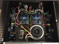
Recently completed my M2X, I build Ishikawa (like official M2) and MtView boards.
To me the Ishikawa and MtView sound pretty similar (but I dont have the most revealing setup), removing C0 from the main board made no audible difference to me.
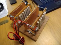
No hum, dc offset at -55mV and -88mV . Did load testing (I build a stereo 7.6ohm load with 13x15W ceramic resistors/channel) at max power. No blown fuses or anomalies.
And most important, sounds great.
I am very happy with the amp. But I did order the Aleph J boards because I like the ACA very much, so I am curious how Aleph J will sound in comparison.
Thanks for all the help, I still cant believe I finished it without blowing it up.
Recently completed my M2X, I build Ishikawa (like official M2) and MtView boards.
To me the Ishikawa and MtView sound pretty similar (but I dont have the most revealing setup), removing C0 from the main board made no audible difference to me.
No hum, dc offset at -55mV and -88mV . Did load testing (I build a stereo 7.6ohm load with 13x15W ceramic resistors/channel) at max power. No blown fuses or anomalies.
And most important, sounds great.
I am very happy with the amp. But I did order the Aleph J boards because I like the ACA very much, so I am curious how Aleph J will sound in comparison.
Thanks for all the help, I still cant believe I finished it without blowing it up.
Attachments
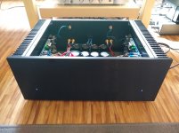
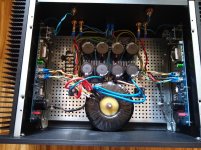
Pieter, what a beautiful build! Congratulations. Your transformer + supply PCB is a lovely snug fit within the front-to-back size of the chassis. Well done.
Mark Johnson
Mark Johnson
Thanks
I also took your recommendation for inrush capacitors (230V mains), I used the SL15 60002 instead of the popular CL60.
I also took your recommendation for inrush capacitors (230V mains), I used the SL15 60002 instead of the popular CL60.

I m thinking of upgrading my current CRCRC ps for my M2X, may i know if its safe to run about +/- 28Vdc rail voltages.
Thanks
Thanks
M2X survived the initial +/- 30.5Vdc power up using SLB with 24-0-24vac trafo.
The 500VA trafo actually produced 26Vrms, so 30.5vdc is the lowest that i can adjust from the SLB ps.
It is singing.

The 500VA trafo actually produced 26Vrms, so 30.5vdc is the lowest that i can adjust from the SLB ps.
It is singing.
M2x MOSFET not getting biased
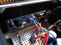
I have been working on this for a while now and still can't figure it out. I have checked and rechecked everything. It all seems to be correct. I probably missed something. I have one working board and one that won't bias. I took off the input stage just to be sure , but that didn't change anything.
I have included a picture of the schematic with the measured board voltages. The bad board voltages are highlighted in red. The voltages were taken after the good board comes up and the voltages drop from +/- 25V to +/- 22.7 V. If I unplug the good board the rail voltages stay at +/- 25V for the bad board.
The good board MOSFETs turn on the heat sink heats up. I was able to zero out the output and run signal through it.
Hopefully someone else has seen this. I'm sure I will say duh! after I find the answer. Any help or advice will be greatly appreciated.
Shared album - Steve Logan - Google Photos
Last edited:
M2x MOSFET not getting biased
I have been working on this for a while now and still can't figure it out. I have checked and rechecked everything. It all seems to be correct. I probably missed something. I have one working board and one that won't bias. I took off the input stage just to be sure , but that didn't change anything.
I have included a picture of the schematic with the measured board voltages. The bad board voltages are highlighted in red. The voltages were taken after the good board comes up and the voltages drop from +/- 25V to +/- 22.7 V. If I unplug the good board the rail voltages stay at +/- 25V for the bad board.
The good board MOSFETs turn on the heat sink heats up. I was able to zero out the output and run signal through it.
Hopefully someone else has seen this. I'm sure I will say duh! after I find the answer. Any help or advice will be greatly appreciated.
photos.app.goo.gl/jdCEZH7evaS3r2988
M2x MOSFET not getting biased
Thanks for the reply Zen Mod,
Of course I figured it out shortly after I posted. The voltage between R8 and Q5 was the same as between R7 and Q5. So the CB3 cap must be shorted. I think I probably heated it up too much when I installed it. The 1uF cap read 20 ohms with the multi meter. I replaced it with another cap and now it works.
An externally hosted image should be here but it was not working when we last tested it.
I just finished my M2x and have little bit hum too. I think that edcors picking power tranny hum. So my next step is to try Mumetal shielding.
I ordered this Trafo shielding sheet, 14,90 € and no more hum. i like MountainView input stage.

I used same double layer shielding from DonAudio (steel = poor mans Mumetal). It seems to work. I have Edcor shielded with Mumetal.
Another M2X for this world
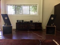
After about a months worth of spare time on the bench she is now warm and breathing music in my system. It has a Mountain View input buffer. None of the top end clinical harshness of the F5 just smooth creamy music.
Thank you Mr Pass for your generosity to this forum and Mark Johnson and 6L6 for making his generosity comprehensible and straightforward for us mere plebeians. If anyone is thinking about building a First Watt amp I can definitely recommend this one.
Attachments
Steve Duffy,
Congratulations on successfully completing your project.
Would you mind telling us more about your audio chain? Like speakers, preamp if any, source.
Congratulations on successfully completing your project.
Would you mind telling us more about your audio chain? Like speakers, preamp if any, source.
OK here we go. Sources are an old Rega Planet with the Rega DAC on the digital side. a Rega RP6 with an Exact cartridge a Tangospinner subplatter and a Jasmine 2.0 phono preamp. The line stage preamp is a NZ DJW (David Watson) SIT based circuit. The signal is spit to a M2X for mid and treble and an old refurbished Quad 606 power amp which is crossed via a miniDSP for the bass. The M2X feeds a lightly crossed open baffle MarkAudio Alpair 12P and a Fountek Neo3 tweeter in a baffle of my design. The bass is handled by Eminence Beta 15A in Martin King style H-frames. Hope that helps
Attachments
Last edited:
- Home
- Amplifiers
- Pass Labs
- The diyAudio First Watt M2x