Hi,
Another way is to measure voltage at speaker terminals @50 Hz and set to e.g 2.8 Vrms. Then if driver is let's say x dB@2.8V efficient at frequency of interest level is approximately known. 50Hz needs to be measured because normally multimeters are inaccurate at higher freqs.
I find this way more convenient to use when high precision is not needed, because it's only necessary to do once by marking position of volume control.
Also room acoustics and SPL changes are sort of irrelevant with this method.
Regards
What I meant to say is there is an REW thread... the mind was tired and the fingers were moving on muscle memory...I think there is an ARTA thread... it might be helpful to read through it perhaps?
Another way is to measure voltage at speaker terminals @50 Hz and set to e.g 2.8 Vrms.
Yes, it is very useful to use a 50 or 60 Hz sine wave to set voltage levels. Normal ordinary volt meters are most accurate at 50-60 Hz.
Hi again,
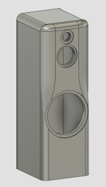
Been busy so a bit slow going for the moment. Current design attached. Ignore the fillets on the top not being perfect, still working out how to draw them properly in fusion360.
Going to have a compartment right at bottom to mount the FA253 Horizontally, then route some slots for ventilation above it.
Then there will be the compartment for the 12", and the top for the Tweeter & Mid.
Thoughts on the design?
Thanks again!
Attachments

Hi,
From drawing it's not apparent how bracing looks like. For panel resonances you might consider adding bracing after boxes are done. Tapping with a palm reveals which surfaces are problematic. Standing waves can be reduced using non-paralell surfaces or filling. Filling is the most effective at velocity maximum(e.g middle of longitudinal direction).
Regards
Hi,
I haven't drawn in bracing yet, that was going to be a question I'd ask along with general stuffing etc, it was more a looks thing at this stage to see what people thought. Thankyou for the Info thought, much appreciated
I haven't drawn in bracing yet, that was going to be a question I'd ask along with general stuffing etc, it was more a looks thing at this stage to see what people thought. Thankyou for the Info thought, much appreciated
The shape of the baffle in post #83 is about as good as it gets from the standpoint of diffraction control, for a large wide cabinet. If you can post some dimensions, I can work up a baffle simulation for the drivers. I would need the overall width and height of the cabinet, the edge radius along the top the baffle, and the width of the flat baffle region at tweeter level. It appears the flat baffle region is about 20 mm wider than the midrange, perhaps?
A baffle diffraction simulation would help as a sanity check to make sure we don't have multiple diffraction effects adding together in a bad way. It is unlikely this would happen, but it is good to check.
Bracing and structural damping will need to be carefully thought out for this design. You have a single large cabinet that will be energized by both a woofer and a midrange, over a frequency band that extends from 20 Hz to ~ 2 kHz. What cabinet material / thickness are you planning to use?
did you know these:Thoughts on the design?
https://pkaudio.webnode.cz/ellips-p/
Edit - just saw post #11 ...
A lot of incredible great and wonderful work, effort and thought has been put into that.
Also your design as well! @neo004 👍 😎
Not to crash the party, but from a very practical point of view, it shows again why a monitor type speaker with a couple of subs is just often better to combine.
Now we are fighting against what acoustically works well and what aesthetically looks good.
Not to mention how very tricky compound chamfers are to make.
@hifijim
I'll take some dimensions off the drawing later on today and post them up, at work at the moment so I'll tackle it when i can.
The front baffle will be 3 x 16mm think MDF laminated to get the thickness for the roundover.
The rest of the cabinet will be 18mm MDF.
@stv
Yes that was my inspiration for these speakers, love the way those speakers came up.
@b_force
Thanks 🙂
I'm trying and learning at the same time, Haven't used Fusion 360 for a few years, so trying to get my head around it again.
Well as for the acoustics vs aesthetics, I need to make sure the sound is the goal as i've spend a fortune on amps/drivers and want the best
result from it. If i need to go back to a bookshelf & separate enclosure for the 12" then thats what i'd rather do.
I've just built a monstrous 18" sub for home theater duties, but was aiming these speakers as a musical setup, something that would be happy in a 2 way setup.
If I'm chasing my tail aiming to design something that won't be ideal, feel free to guide me in a different direction.
Thanks again all, really appreciate the help.
@hifijim
Some measurements for you...
Overall cabinet size is 386mm wide x 1130mm high x 413mm deep
Edge of tweeter to start of side roundover is 43mm, 3mm down from top roundover
Edge of Mid to start of side roundover is 12mm
Width of flat face of baffle between starting edges of roundover is 190mm
Top roundover radius is 45mm
Side roundover radius beside tweeter and mid is 130mm wide (not a uniform radius)
Centre of tweeter to centre of mid is 140mm.
If you need anything more just let me know.
Thankyou 🙂
Hi,If I'm chasing my tail aiming to design something that won't be ideal, feel free to guide me in a different direction.
There is no ideal speaker, and all about compromises : )
One small issue is perhaps the transition from 6" to a direct radiating tweeter IMO. Change in diameter is large, so will be change in directivity. Maybe it's not a big deal and gonna sound good. It should be tested with your drivers.
More things to consider later, when cross overs will be designed :
a) I think it's important to align phases amongst any two drivers in such a way, that at X-o frequency difference is less than 10 degrees or so, and within 20 degrees one octave below and above transitional frequency. I can not back my claim by theoretical explanation, but subjectively aligning phases makes the system more relaxing to listen IMO.
b) It's ok. to have dips in frequency response but not peaks. So it's good to measure at different angles and see. Anything above maybe +1.5 dB can be audible and ideally should be adressed
c) Some inepensive mics have significant deviations, especially at high freqs, and quite high noise floor. So measurements should be taken with a grain of salt unless 100% sure environment and equipment is really up to the task.
Regards & good luck
Here is the baffle diffraction simulation based on the information you provided. I used VituixCad.
You have a different size edge treatment on the top than on the sides. VituixCad simulates all four edges the same, so we have to choose which size radius to use for each driver simulation.
For the midrange, the width of the radius/bevel region is 98 mm wide [ (386-190)/2 = 98 ].
For the tweeter, the width of the radius/bevel region is 98 mm wide in the horizontal plane, and 43 mm in the vertical plane. I ran the simulation both ways.


I do not see any diffraction related complications at this point. The diffraction hump on the midrange is small. The tweeter high frequency diffraction is very mild.
At a crossover frequency of 2k, there will be a mismatch in directivity between the tweeter and the midrange. In these idealized simulations it looks like about 3 dB difference in directivity. When I look back to my actual measurements of a TW29TX and MW16TX, the difference in directivity was about 2 dB... the TW29TX has higher directivity than predicted by an idealized piston it seems. I expect you will have about the same. So this will be something that you will have to manage with driver spacing and the crossover, but 2 dB difference in directivity index is a very manageable challenge, not a show stopper. In my case, I used as low a crossover as the tweeter could tolerate (1.6k 4th order) to get the directivity matching as close as possible.
So all in all, I don't see any issues at all. That is not to say that the shape is fully optimized. There are probably some improvements that could be made, but your first attempt at a baffle design has a high potential.
j.
You have a different size edge treatment on the top than on the sides. VituixCad simulates all four edges the same, so we have to choose which size radius to use for each driver simulation.
For the midrange, the width of the radius/bevel region is 98 mm wide [ (386-190)/2 = 98 ].
For the tweeter, the width of the radius/bevel region is 98 mm wide in the horizontal plane, and 43 mm in the vertical plane. I ran the simulation both ways.
I do not see any diffraction related complications at this point. The diffraction hump on the midrange is small. The tweeter high frequency diffraction is very mild.
At a crossover frequency of 2k, there will be a mismatch in directivity between the tweeter and the midrange. In these idealized simulations it looks like about 3 dB difference in directivity. When I look back to my actual measurements of a TW29TX and MW16TX, the difference in directivity was about 2 dB... the TW29TX has higher directivity than predicted by an idealized piston it seems. I expect you will have about the same. So this will be something that you will have to manage with driver spacing and the crossover, but 2 dB difference in directivity index is a very manageable challenge, not a show stopper. In my case, I used as low a crossover as the tweeter could tolerate (1.6k 4th order) to get the directivity matching as close as possible.
So all in all, I don't see any issues at all. That is not to say that the shape is fully optimized. There are probably some improvements that could be made, but your first attempt at a baffle design has a high potential.
j.
Thats fantastic info, thankyou both.
I will aim over the weekend to get the top half of the front baffle made up as a test baffle and do some measurements.
Is there a particular guide i can follow as to how to take these initial measurements? Eg. Do i do a measurements sweep of each driver, with no crossovers or do i put my initial crossover in place then take measurements? Also I have a 3.5m x 4m x 2.4m high room in the shed fully insulated, walls, ceiling, carpet floor, it sounds quite dampened in there, would that be any good for measurements? Or should it be in the room it will actually be in or outside? I can measure wherever suits best.
Thanks heaps!
Are you familiar with the process of making a nearfield scan of a driver (with no time window) and saving the impulse response... Then making far field scans (with a short time window) of the driver at various polar angles , and saving each of those impulse responses. Then using a software to merge them together, including an adjustment to convert the near field response from 2-pi (infinite baffle) to 4-pi (open space)... ?
At this time, all your measurements will be a raw driver response. Do you have a test amp or will you be using the Hypex FA253?Is there a particular guide i can follow as to how to take these initial measurements? Eg. Do i do a measurements sweep of each driver, with no crossovers or do i put my initial crossover in place then take measurements?
The room does not make much difference, because you will use the near field scan to capture low frequency response. The high frequency part (far field) uses a short gate, on the order of 4 to 5 ms, to minimize the effects of reflections.Also I have a 3.5m x 4m x 2.4m high room in the shed fully insulated, walls, ceiling, carpet floor, it sounds quite dampened in there, would that be any good for measurements? Or should it be in the room it will actually be in or outside? I can measure wherever suits best.
https://kimmosaunisto.net/ Look at the " VituixCAD_Measurement_REW.pdf" on that site
This is a good reference also
This is a good reference also
Attachments
I'm very green with proper measurement taking.
All I've really done is just some general sweeps in REW just experimenting.
I'll have a read up on those documents and have a go at it
Edit: - I do have another amp there for testing
All I've really done is just some general sweeps in REW just experimenting.
I'll have a read up on those documents and have a go at it
Edit: - I do have another amp there for testing
Last edited:
Well I have learnt a lot already, i realise there is much more to learn but i'm keen 🙂
Thankyou for all your help
Thankyou for all your help
I'm very green with proper measurement taking.
All I've really done is just some general sweeps in REW just experimenting.
I'll have a read up on those documents and have a go at it
Edit: - I do have another amp there for testing
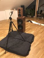
While doing measurements in typical room, at least put something on the floor and move speaker as far as you can from any hard surfaces. Normally measurements are done with time window to exclude reflections as much as possible. If you can afford 80 euros, ARTA is highly recommended.
Regards
Attachments
Doing many (maaaaany!) measurements and trying (or failing) to interpret them is where I learned the most.
Give yourself plenty of time to do "unnecessary" measurements just to get some practise.
then do the "final" measurements to simulate crossovers and continue the loudspeaker project!
Give yourself plenty of time to do "unnecessary" measurements just to get some practise.
then do the "final" measurements to simulate crossovers and continue the loudspeaker project!
- Home
- Loudspeakers
- Multi-Way
- SB Acoustics 3 way active build - Advice