For external Fusion boxes I made these for the FA122. Inspired by some I saw at Spiritland in London. Cooling should be fairly good and the look nice on a shelf (if you have nice cables). I bridged these to run them as stereo amps but the terminal cups could easily be changed for active or Speakon for single wiring to speakers.


Also, Hypex always seemed to favour balanced input, I used to run these with a NAD658, its a pretty good pre-amp and I bought for a few reasons.
1. Balanced outputs 2. it is Roon Ready with Display. 3. It has 2 sub outs. 4. Most importantly It has Dirac Live so you can room eq speakers with all sources, including the subs.
If you are buying the best components, the best plate amps and building the best cabinets, the room may still suck...
1. Balanced outputs 2. it is Roon Ready with Display. 3. It has 2 sub outs. 4. Most importantly It has Dirac Live so you can room eq speakers with all sources, including the subs.
If you are buying the best components, the best plate amps and building the best cabinets, the room may still suck...
Nice looking amp enclosure...
@PKAudio - I was going to mention the elliptical edge on your baffles. thanks for bringing it up.
An alternative to an elliptical edge is a 30 degree bevel with radius transitions instead of a sharp corners. This also reduces the need for very thick baffles. I doubt there is much performance difference, it comes down to what is easier to construct.
@neo004 - I did not want to leave you with the impression that your USB mic would not be useful. When you get a 2-channel audio interface set up with a mic, there are many "moving pieces", things which need to be adjusted and calibrated. Your USB mic will be very useful in cross checking your setup.
In general it seems to get the tweeter and mid as close together as possible, so i've worked on that.
I did some reading on the mid to bass spacing and it was to be max 1/4 wavelength, so i've worked on that too.
Before you get too far down this path, I want you to consider a wider spacing.
My TXT build was designed and built before I started doing simulations with VituixCad, before I was modeling the power and directivity response of the whole system. I spaced my MW16TX-4 and the TW29TNX-B very close together. The CtC spacing was 146 mm, with just 12 mm spacing between them.
The result was a dip in the power response near the crossover frequency. This also shows up as a hump in the Directivity index. It is not a particularly bad hump, about 2.7 dB. But it means that my speakers are a bit finicky in the lower treble region. I use 3 different presets on the Hypex amps with 3 slightly different treble balances, depending on the recording. It also means the speaker is a little sensitive to where it is placed in the room.
If I run my simulation today with a wider spacing, I can reduce the hump in the DI curve to the point where it is virtually insignificant. With a 250 mm CtC spacing, the DI curve has 1.5 dB hump, with no change to the on-axis curve. Based on my experience with other speakers I have built, I think this small 1.5 dB DI variation would be inaudible in my room.
250 mm is about equal to 1.2 x the wavelength of the crossover frequency (1600 Hz).
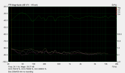
When the DI curve is almost flat from 500 - 5k, it is possible to optimize the EQ to get really nice compromise between the on-axis response and the Predicted In Room (PIR) response, shown in my final plot. I have found that, in my room, a speaker like this does not need 3 different presets for 3 different EQs.... And it is less sensitive to room placement.
If I was going to re-build this speaker, I would use a larger CtC spacing, probably 250 mm. I will warn you ahead of time, it looks strange, and people will question your sanity. But it works well.
Hi,
I think that acoustic power response is mileading because it shows averaged f.r response over all directions as opposed to exact listening angles.
Attached simulation of 150 vs 250 mm spacing between mid range and tweeter. According to this Interference patterns generate much deeper valleys when spacing is larger. It's sorta possible to play with spacings but most often the closest one gives the best overalll results IMO, and because of that it's normally done in this way.
Another way to improve upon cross over point is using asymmetrical fileters. E.g mid range is cut at 12 db/Oct while treble uses 18 db/Oct filter. Somtimes it makes for much better transitions compared to theoretical filters of same slope.
At the end it boils down how output from different sources combines over frequency range because of phase shifts.
Regards
Attachments

Here are the results I get for the two CtC spacings. This is vertical polar responses, 0 to 90 degrees (up) and 0 to -90 degrees (down). It seems to me that with the narrower spacing, much of the vertical cancellations line up on 1.6 kHz, and this is a big contributor to the power response dip. It is not just power response, it is also the Early Reflections (ER). With the wider spacing, the nulls are spread in frequency, and not as deep.
All these sims use a 4th order 1.6k crossover, which I found sounds best with these two drivers, in this cabinet, in this room, using my ears.


j.
All these sims use a 4th order 1.6k crossover, which I found sounds best with these two drivers, in this cabinet, in this room, using my ears.
j.
Hi again,
It's interesting. Normally simulations predicted closest spacing possible gives the best results. Likely the choice of crossover design plays a great role here. Furthermore, as mid-range driver would generate some out-of band noise(harmonics, etc.), it's a bit risky to build system with wide spacing before testing in a draft box IMO. As sometimes ear starts to register different sound sources which is not optimal.
Regards
I have designed and built several systems with 1.2xwavelength spacing. I made several test cabinets from XPS foam board to verify this strange wide spacing actually works.
https://www.diyaudio.com/community/threads/compact-low-cost-active-3-way-speaker.402812/post-7440893
https://www.diyaudio.com/community/threads/tall-thin-2-way-for-workshop-pc.402268/post-7426447
https://www.diyaudio.com/community/threads/new-project-tower-3-way-with-twin-8s.378223/post-6816455
It looks so strange because of the low crossover frequency drives a wide spacing. If the crossover frequency were 3k, then with the drivers touching the Ctc would be 135 mm... and at 3k, that would be 1.2 x wavelength. 3k would not work with a 6" driver because it has such high directivity at 3k... But with a 4" driver such as the Scanspeak 10F, 3k would work great, and a 135 mm CtC spacing would not look odd at all.
The TW29BN tweeters can handle a 1.6k 4th order crossover. Distortion is low, and clarity and detail is excellent.
Side topic:
To fairly compare the effect of varying the crossover frequency, the CtC spacing must also be proportionately varied. Otherwise most of what we would hear and measure would be simply the change in wavelength spacing.
There is a widely accepted line of thought that the crossover frequency between a mid and a tweeter should be outside of the range of instrument fundamentals, which means crossover frequencies of 4k or so. I am convinced that much of this preference stems from placing the small mid and tweeter touching... and at that spacing, a 1.2 x wavelength crossover frequency is about 4k. The only way to fairly compare this situation to a 2k crossover is to increase the CtC spacing, but I suspect that is rarely done.
Hi again,
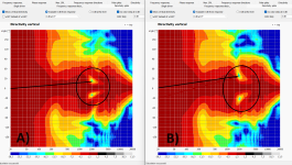
I just made a simulation of two systems. X-o frequency about 2 kHz.
A) spacing of 220 mm.
B) Spacing 150 mm.
It can be seen that low output zones move closer to center line with bigger distance beetween centres, see screenshot. This implies that by moving drivers closer or further one can design system based on expected listening angles. Which is different depending on speaker height, etc.
Now about crossover frequencies. As you said it's typically not recommended to cross below 3 kHz. I am not convinced by that too. But in practive I've seen systems which sound worse with X/O < 3 kHz. Testing revealed that tweeter distorted at 2-2.5 kHz and below. So this "rule of thumb" may actually arise from tweeters being overdriven. Add to this some exotic 6 dB/octave filters and the higher cross over the better it would sound : ).
Regards
Attachments
Last edited:
The TW29BN tweeters can handle a 1.6k 4th order crossover. Distortion is low, and clarity and detail is excellent.
It's interesting to hear. According to hi-fi compass distortion figures I see about 1.5% THD @ 2kHz at a level of 2.83V.
This is nothing to write home about and IMO this driver is heavily overpriced.
Regards,
Lukas.
Attachments

THD is nearly worthless as an indicator of sound quality. Odd order harmonic distortion is much more relevant. Look at the HD3, and it is extremely low. 2.83 V with this driver is about 96 dB SPL at 1 m, so this driver's distortion is low when compared to other dome tweeters operating at 96 dB SPL.
This is the tweeter that @neo004 has chosen, so whether or not you (or I) consider it a good value is irrelevant. Nonetheless I consider it a very good beryllium tweeter for the money.
This is the tweeter that @neo004 has chosen, so whether or not you (or I) consider it a good value is irrelevant. Nonetheless I consider it a very good beryllium tweeter for the money.
Sorry to say but stating what is relevant and what is not in this case is quite ignorant IMO.
After all everyone has it's own taste and preferences.
In the past I have tested a tweeter with similar characteristics(high H2, low other distortions) and did not like the result at all. But others seem to live with that and are happy.
Everyone has a right to have and express his opinion in a polite manner and please respect that.
Regards
If my words came across as rude, that was not my intent. I am sorry. Let me rephrase.
In my opinion, THD is not a very good measure of performance because the calculation is usually dominated by HD2. For most people, HD2 is inaudible below 2%, and even when it is above that and audible, it is not annoying. HD3, HD4, and HD5 are definitely more audible, and more annoying. However, everyone hears things differently, and I am certain there are some people who are particularly sensitive to 2nd order harmonic distortion.
@neo004 has purchased the TW29BN-B tweeter, and I think it is a good tweeter. I have used the very similar TW29TXN-B and the TW29BNWG waveguide tweeter. You said you believe the tweeter is heavily overpriced, and I don't agree. In any case, it does not really matter at this point, because this project is going to use the TW29BN-B.
j.
Hi again,
I agree that H2 is perhaps less audible as compared to higher harmonics in most of cases. Still 1 to 2% is not "low distortion" by any means IMO. If I was the designer of system using TW29BN-B I would consider cross over at 3k or so, since there it seems to be a lot better.
There is an interesting article by Rod Eliott about distortion in amplifiers. There it's stated hamonic & intermodulation distortion is related. Would interesting to investigate/test if that relationship holds for loud speakers. Here is the link :
https://sound-au.com/articles/intermodulation2.htm
By the way, I think that speakers should be designed based on both measurements and listening tests. So it's nice if one can test his combination of drivers in a test box before committing to final design(thats proposal for OP).
Regards
I have the SB Acoustics Satori TW29RN-B, that was half price on eBay. Looking forward to seeing what you build and If the non-berrylium could be a drop in replacement.
Hi again,
I've received my calibrated XLR mic & the UMC202HD. So i'm nearly ready to get started on some measurements.
But first i need to decide on the front baffle. I've been trying to model what I'm after in Fusion 360, as i can then output that to my CNC.
What I'm concerned about is the roundover on the sides, As i'm not using a waveguide tweeter, and the tweeter is quite a bit smaller than the mid woofer, i can't get too close to the tweeter with the roundover before it impacts the mid.
I'm assuming the closer i can get to the tweeter the better, but is there an ideal distance you would want the roundover to start from the tweeter?
Or is it a case of a test baffle and see how the measurements look?
I've marked up a picture to show the measurement i'm talking about. The picture shows the cutout hole, not the tweeter, so the edge of the tweeter would be about 15mm closer to the roundover.
I've decided i'll work on a 45mm thick solid hardwood front baffle, i can get this timber easily from work, its basically furniture grade, so will be nice to work with.
I've already got the drivers in test boxes, but when I get some guidance on those roundovers, i'll make a new front baffle for the box with the tweeter and mid with the roundovers and see how it measures.
Thanks again all, very much appreciate the guidance
Attachments
If you don't need the distance they would probably look more elegant with a continuous curve like the Rockport
https://rockporttechnologies.com/orion/
https://rockporttechnologies.com/orion/
Also any reason you are not using a waveguide? Especially as this could be cnc’d into the baffle?
Hi,
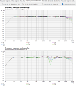
It's not clear if and how rounding of edges will improve the frequency response. The result will likely be marginal(1-1.5 dB) and depends how it combines with cross over and fr. response of drivers. Here attached test results of the same box, same position, same speakers but a) square edges and b) 25 mm rounded edges attached to the same box. As it can be seen in this particular case rounding of edges made the result different by a little(tiny) bit.
So best way is to test it.
Regards.
Attachments

Last edited:
You could increase the radius with height, such that the radius is larger around the tweeter than it is around the midrange. This would probably benefit you.
Without a simulation, it is hard to say. If you are willing to make several test baffles and measure them, you can interpolate between the results and get a good solution without the need for simulation.

Without a simulation, it is hard to say. If you are willing to make several test baffles and measure them, you can interpolate between the results and get a good solution without the need for simulation.
- Home
- Loudspeakers
- Multi-Way
- SB Acoustics 3 way active build - Advice