Happy to buy ARTA, and i've got a big main living room, so i can easily move the speakers to somewhere suitable.
I use ARTA, and I like it. But many people prefer REW. Study them both before you make up your mind.
Not sure if you still can buy a license for ARTA 🙁
REW is fine, just the interface gives me the feeling I want to throw my computer at the wall.
REW is fine, just the interface gives me the feeling I want to throw my computer at the wall.
Just to confirm, the testing i will do will be in a test baffle with the correct size roundovers, with just the tweeter and mid mounted in the baffle?
No enclosure yet at this stage, then do the test on each driver individually?
Thankyou!
No enclosure yet at this stage, then do the test on each driver individually?
Thankyou!
Without midrange enclosure you will not see it's correct low end (which may be totally ok, you can use the simulated response) and you won't see any effects of enclosure resonances and dampening, which in my opinion could be quite useful to include.
Ok thanks for that. So for the enclosure then, when i done some really early experimenting I made enclosures for the tweeter and mid, I just modeled the box in Win isd to have a Q of .7 for the mid and just made an empty box. No stuffing etc, Which i know isnt correct, i just couldnt wait to test things lol
It worked out at 9litres from memory,
So i'll remake an enclosure tomorrow and use the new test front baffle.
Am I correct in using the enclosure size based off Winisd? Or is that more just for subwoofers?
It worked out at 9litres from memory,
So i'll remake an enclosure tomorrow and use the new test front baffle.
Am I correct in using the enclosure size based off Winisd? Or is that more just for subwoofers?
a midrange enclosure with a Qtc of 0.7 is fine... although a Qtc anywhere from 0.5 to 1.0 is fine. You need some damping or the standing wave modes will radiate back through the cone and create an odd response. It does not have to be perfect at this stage, just some foam or rockwool, even the stuffing from an old pillow will work.
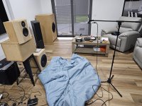
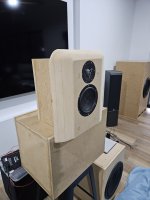
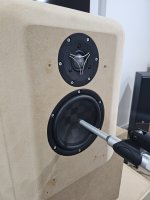
Well I've been very busy. Got my test baffle made, built a box and lined it with some wall insulation i had lying around, glued that to the back of the baffle and thats my test setup.
I read through a heap of guides, some are hard to follow, I found this probabaly the easiest for my Initial testing.
https://www.audiosciencereview.com/...ents-spinoramas-with-rew-and-vituixcad.21860/
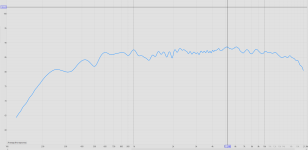
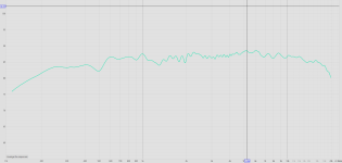
I took the following measurements.
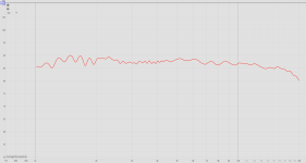
1 - Tweeter, no crossover, 1/24 smoothing (1m on axis)
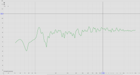
2 - Mid, no crossover, 1/24 smoothing (1m on axis)
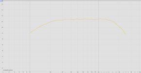
3 - Mid, nearfield, no crossover, no smoothing (Nearfield)
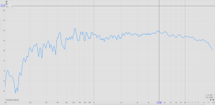
4 - Tweeter and mid, crossovers in place, 4th order 200hz, 4th order 1.6khz, 1/24 smoothing (1m on axis)
5 - Same as above, but gated to avoid first major reflections, 1/24 smoothing
6 - Midfield Measurement and full spectrum measurement merged in rew (Trace Arithmetic B to A at 400hz) (Just following the guide from the website,
this measurement may or may not be correct or relevant)
All measurements were taken in REW, using the UMC202HD, Dayton EMM-6 XLR Mic. At the level of the tweeter, @1m for most measurement, or approx 10mm from mid for nearfield measurement.
So where to from here?
I'm assuming i need to take off axis measurements to see any effect of the baffle?
I have to work on a rotatable platform now so i can work towards those measurements.
If the off axis results seem ok, can i then basically build the whole speaker, then its just down to finalising the crossover once
the speaker is assembled?
Thanks again, some pics attached.
I read through a heap of guides, some are hard to follow, I found this probabaly the easiest for my Initial testing.
https://www.audiosciencereview.com/...ents-spinoramas-with-rew-and-vituixcad.21860/
I took the following measurements.
1 - Tweeter, no crossover, 1/24 smoothing (1m on axis)
2 - Mid, no crossover, 1/24 smoothing (1m on axis)
3 - Mid, nearfield, no crossover, no smoothing (Nearfield)
4 - Tweeter and mid, crossovers in place, 4th order 200hz, 4th order 1.6khz, 1/24 smoothing (1m on axis)
5 - Same as above, but gated to avoid first major reflections, 1/24 smoothing
6 - Midfield Measurement and full spectrum measurement merged in rew (Trace Arithmetic B to A at 400hz) (Just following the guide from the website,
this measurement may or may not be correct or relevant)
All measurements were taken in REW, using the UMC202HD, Dayton EMM-6 XLR Mic. At the level of the tweeter, @1m for most measurement, or approx 10mm from mid for nearfield measurement.
So where to from here?
I'm assuming i need to take off axis measurements to see any effect of the baffle?
I have to work on a rotatable platform now so i can work towards those measurements.
If the off axis results seem ok, can i then basically build the whole speaker, then its just down to finalising the crossover once
the speaker is assembled?
Thanks again, some pics attached.
Attachments
-
 1.png22.2 KB · Views: 145
 -
 2.png33.2 KB · Views: 120
 -
 3.png19.9 KB · Views: 118
 -
 4.png40.3 KB · Views: 116
 -
 5.png27.3 KB · Views: 103
 -
 6.png25.8 KB · Views: 127
 -
 20240407_171621.jpg638.6 KB · Views: 154
 -
 20240407_171628.jpg367.5 KB · Views: 147
 -
 20240406_152220.jpg490.2 KB · Views: 143
 -
 20240407_154219.jpg448.9 KB · Views: 139
Hi,
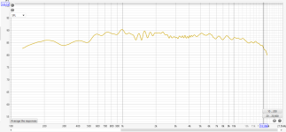
The frequency reponse irregularities that you are seeeing are typical for measurements in the room. Not so much can be done about that.
I have found out that measuring at about 50 cm from the speaker is sort of good compromise, so room influence is a bit less than at 1 m and also distance is large enough to see how drivers interact over cross over frequencies.
I see you are using celullose-filled fiberglass(perhaps knauf) ? If so, it's a light filling and it's safe to fill the box completely. Lining the walls is less effective, because it tends to absorb only freuquencies where lining thickness is perhaps 1/2 of wavelenght or so.
I think that crossing the tweeter you are using at 1.6 kHz is too low. Suggestion to also try other frequencies, perhaps 2 & 2.5 kHz and test how it measures and sounds. Maybe in theory off axis response is better when crossed lower, but also tweeter is loaded much more and can start to distort at higher volumes.
Normally, fine-tuning of the cross over can always be done(and IMO is the best to) do in final phase, when box is in final shape.
When testing off-axis, look if there are no peaks at X-O points, as it is something to be avoided.
Regards
Last edited:

The near field mid measurement looks good. The next step forward would be to apply gating to the far field mid measurement, and then merge it with the near field.
To start with, you can apply gating (time window) to the mid driver and tweeter driver far field measurements. If you saved the impulse response as a *.pir file, there is no need to re-measure. Just load the *.pir file into REW or VituixCad.
The ASR post from napilopez is an exceptionally good guide.
Your test baffles look excellent. Nice job on that.
Yes. At this point, there is really no way to know or guess what the final crossover filter shape will be.Normally, fine-tuning of the cross over can always be done(and IMO is the best to) do in final phase, when box is in final shape.
Agree.I think that crossing the tweeter you are using at 1.6 kHz is too low. Suggestion to also try other frequencies, perhaps 2 & 2.5 kHz and test how it measures and sounds. Maybe in theory off axis response is better when crossed lower, but also tweeter is loaded much more and can start to distort at higher volumes.
In my humble opinion, when choosing the crossover frequency of the speakers, you need to rely on the level of distortion of the speakers. I definitely look at the level of distortion of the midrange and high-frequency links, and choose the crossover frequency at which I get minimal distortion from both the midrange and high-frequency links. In my opinion, distortion control is important and distortion is a convenient reference point for choosing the optimal crossover frequency.
a midrange enclosure with a Qtc of 0.7 is fine... although a Qtc anywhere from 0.5 to 1.0 is fine. You need some damping or the standing wave modes will radiate back through the cone and create an odd response. It does not have to be perfect at this stage, just some foam or rockwool, even the stuffing from an old pillow will work.
Read the rockwool MSDS.
The stuff is manmade asbestos.
Thanks DT
Thanks for the info.
Just to clarify. The purpose of me building the test baffles was to see how the roundover radius effects the tweeter, that is something I will only know once i do off axis measurements?
I attempted to combine the far field tweeter & mid. Pic attached.
What product do you recommend lining the walls/stuffing with for the final enclosure, i'll get some of that ordered so i have it ready.
Thank you all!
Attachments
It can be experimented with, but in general filling density between 10 to 15 Kg/m3 is desirable for a closed box. That means rock wools are typically near the high side of filling density, and maybe often too dense. Fiberglass being on low sidde and a safe bet. No need to buy some special pofill or something like that, likely it's going to perform worse(near useless) compared to fiberglass.
Regards
Regards
Last edited:
I have had very good results with natural wool stuffing. As Bazukaz mentions, both fiberglass and rock wool are well regarded. Polyester fiber stuffing can be good if it is the right grade/type. Often the type of polyester stuffing sold at fabric/craft stores is not the right type, and it is inferior. "acoustistuff" is a polyester stuffing which is a good safe choice. Shredded denim/cotton insulation performs well. Melamine foam is very good, the sort that is branded as "basotect" is a good choice.
In my textreme system, I crossed a MW16TX to a TW29TX at 1.6k LR4. This is the measured harmonic distortion

odd order harmonic distortion is below 0.3% from 150 Hz up. The 1.6k 4th order crossover is adequate to protect the tweeter and keep its low frequency distortion suppressed. In truth, my noise floor is masking the true distortion, so it could be lower. But it is at least as low as this plot shows.
https://www.diyaudio.com/community/threads/new-active-satori-textreme.366347/post-6544656
In my textreme system, I crossed a MW16TX to a TW29TX at 1.6k LR4. This is the measured harmonic distortion
odd order harmonic distortion is below 0.3% from 150 Hz up. The 1.6k 4th order crossover is adequate to protect the tweeter and keep its low frequency distortion suppressed. In truth, my noise floor is masking the true distortion, so it could be lower. But it is at least as low as this plot shows.
https://www.diyaudio.com/community/threads/new-active-satori-textreme.366347/post-6544656
Hi,
It's a nice figure, and I think it's really quite good considering especially low XO point. From your data and tests by hi fi compass it looks that indeed the tweeter can handle XO @1.6kHz/90dB/1.4V without a problem of running into high levels of distortion.
However in case of higher drive voltage distortion would raise sharply. That's by about 10 dB for 2.83V/96 dB and IMO is typical of peaks in music while listening on average level. This can be already audible, depending on type of programme material.
The voice coil of a tweeter is tiny. Maybe it can handle a watt, two or so of continuous power unless ferrofluid cooled. Crossing lower means more energy is being fed to this tiny coil, so power compression can definitely become an issue while listening loud. Also power handling is significantly reduced with increased risk of thermal damage.
So what is the big advantage of crossing the tweeter so low ?
Attached link to tests :
https://hificompass.com/en/speakers/measurements/satori/satori-tw29txn-b
By the way, treble response does not seem to match manufacturer data sheet, is it equalized by DSP or similar ?
Regards
Last edited:
In regards to treble response, I'm not sure whats up there. Definately no DSP in place, just the crossovers.
It seems to taper off from 10k. Are frequencies up that high effected by the room as much as low end?
It seems to taper off from 10k. Are frequencies up that high effected by the room as much as low end?
As I recall from SB datasheet, the tweeter you are using should drop a little above about 10k. I sort of like this idea, because it makes speakers less bright. Others may dislike. Kind of matter of taste.
The way room interacts in low vs mid/high frequencies is different. In case of bass it's mostly standing waves in the room. For treble it's reflections from hard surfaces. Reflected waves interact with direct sound and can cause deep suck-outs or some peaks. This effect may be quite significant and change a lot when mic is moved as little as few centimetres.
So treble is significantly affected too, it depends on surface characteristics of the room, listener position etc.
Regards
- Home
- Loudspeakers
- Multi-Way
- SB Acoustics 3 way active build - Advice