Mooly; just finished studding your post 171 again, and rechecked my voltage reading on 6217 and it should say 6217 c +1.0v. 😱
I am wondering, supposing these voltages I have taken were to be (should read) as in the service manual, for this type of test setup (nothing attached) 😕
If this was so then if we would be looking at ones, with no voltage readings; 6229 b & c, 6230 b & c, 6231 e b & c, 6232 b & c, 6234 c, and ones showing reverse polarity 6217 b, 6229 b & c, 6230 b & c, 6231 b & c, 6232 b & c, 6235 c.
lets say ones connected to a transistor; see below
To do. From what I have picked up on this investigation; a loss of gain is the most possible cause/fault and maybe caused by a faulty transistor How about checking the likely ones or all of them, can they be checked on board 
Can we undertake this first
To do. Board B voltage have not been fully checked this is the last board; need to check these next
Done. Board C voltages, was fully checked last week and was good
Don’t know. Board A seems to be uncheckable for any fault
I do have a Fluke 73; I thought you were inquiring about a meter that would buss on low voltages, the new meter will buss on and above 110+v, I realise now this is not what you meant, my Fluke should do if the reading is above mV it should then follow-on and read volts. My Philips CD 751 player is an old one before mp3’s came out.
A hearty thanks to you all
I am wondering, supposing these voltages I have taken were to be (should read) as in the service manual, for this type of test setup (nothing attached) 😕
If this was so then if we would be looking at ones, with no voltage readings; 6229 b & c, 6230 b & c, 6231 e b & c, 6232 b & c, 6234 c, and ones showing reverse polarity 6217 b, 6229 b & c, 6230 b & c, 6231 b & c, 6232 b & c, 6235 c.
lets say ones connected to a transistor; see below
To do. From what I have picked up on this investigation; a loss of gain is the most possible cause/fault and maybe caused by a faulty transistor
How about checking the likely ones or all of them, can they be checked on board Can we undertake this first
To do. Board B voltage have not been fully checked this is the last board; need to check these next
Done. Board C voltages, was fully checked last week and was good
Don’t know. Board A seems to be uncheckable for any fault
I do have a Fluke 73; I thought you were inquiring about a meter that would buss on low voltages, the new meter will buss on and above 110+v, I realise now this is not what you meant, my Fluke should do if the reading is above mV it should then follow-on and read volts. My Philips CD 751 player is an old one before mp3’s came out.
A hearty thanks to you all
Board A can be declared good if there is continuity from the input socket you are using (L or R) and point C402. Stick your meter lead into the centre of the phono socket in use and check there is a 'dead short' between there and C402.
Even if there was a faulty transistor you would be unlikely to pick it up from measuring them in circuit. The results can be subtle and need interpretation. The best guide to a faulty one would be in the voltage readings... even that occasionally (0.5% of the time) is not definitive though.
The marked voltages on 'B' board look about right although you will find slight differences between measured and marked. That's normal and depends on things like the absolute value of the power supply voltages and the characteristic of the individual transistor.
The MP3 file can be 'burned' to a recordable CDR (not a CDRW as your Philips almost certainly wouldn't play those). CDR is supposed to be playable on pretty much 'any' CD player. You would record the disc on a PC/laptop using Windows Media Player to create an audio CD from the MP3 file.
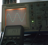
I thought I better just 'prove' that an ordinary DVM would work for this 🙂
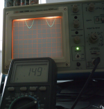
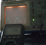
Here is 440Hz tone displayed on the scope and on the meter together with a DC offset of positive an negative voltage (last two shots). Surprisingly the meter (this one at least) was not fazed by the DC which means that in this case no series cap would be needed.
The values of DVM measured signal and the scope agree. 149 millivolts RMS reading on the meter is corresponding the 420 millivolts peak to peak displayed on the scope.
Attachments
I believe there should be some voltages.
Tracking (see page 9 the drawing you most use) the transistors with no voltages (all of them connect from the first to last, no coincidence?) backwards from 6232, 6231, 6230, 6229 after that is a cross road, a diode 6244 BAW62 this would let forward voltage from ground (there shouldn’t be any voltage on ground), so if I turn right, you come to 3285 a 100k top side giving + 25 or 35v, bottom side giving +1.1v or 1.4v.
From the cross roads go straight on; you come to V2 (leads to 6223 these volts are good), and V3, follow V2 to the cross roads, take the voltage readings from that point and the top side of 3261 there should be around 30mV. V3 leads to a cross road, take the voltage readings from that point and the top side of 3260 there should be around 15mV.
I am proposing to check these voltages as a starter; what do you think, I am expecting to find something wrong? Bearing in mind I am running out of time? I have to start somewhere?
Please advise on this.
Thank you for posting the images showing the usefulness of the DVM and that there would be no need to use an add-on capacitor; I am assuming that this test would need the pre-amp, cd player rigging to this speaker and with it all connected and playing the cd, start to take voltage readings and then we have to do individual tests?
Easy one first. To use the test tone you just have the whole system (well that speaker) coupled up as you would for normal listening. You could then measure the actual signal voltage present along the way.
The transistors 6229 through to 6233 and the diodes form a circuit that amplifies greatly any signal from the main amplifiers. It has only one function, to detect audio and close the relay when that audio is present. If there was any problem in that area then the relay would not be closing and you would not be getting any sound at all.
The other voltages (around 6223) we have checked. The single most critical thing is that the voltage at the output of all three amplifiers is at zero volts DC (zero as in no more than around -/+ 0.1 volts). So that is the junction of those 1.2 ohm resistors (and the same location for the other two virtually identical amplifiers)
If your meter can measure the AC signal I think using the tone could be the best way to find this problem. All you need is a CDR and burn it in media player. Vista, W7, W8, W8.1all allow you to do that directly (not sure on XP).
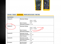
I looked up the Fluke the other day, that's where I got those figures from on its sensitivity.
Just on a tablet at the moment so I'll have another look later.
Just on a tablet at the moment so I'll have another look later.

440 Hz test tone now on CD-R and have tried it out on Windows media player; it sounds OK so good to go, so now, need to prepare for testing with a procedure 😕
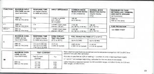
Attached Fluke 73 specifications; yes mine looks like your picture.
Attached Fluke 73 specifications; yes mine looks like your picture.
Attachments

Last edited:
That's great. You burned it as an audio disc ? (not a data disc) so it will play on your Philips set up. Yes 🙂
Here's what we do. You have it all connected as in normal use and you then play the tone and turn up the main amp volume until you can hear it. Just as if you were playing music. Make sure the sensitivity control is set correctly.
1/ Now measure the AC Voltage on C402 and write it down. For example 103mv.
2/ Measure the AC voltage on 6400 emitter. What is it ?
We work through the whole circuit like this measuring on 6400 emitter and 6401 emitter first.
And start at low volume... if its to loud to be comfortable then we can turn the three presets down while testing it all to quieten things down.
Yes, AC volts. The Fluke is auto ranging and should select the correct range automatically when it sees the voltage.
Take it slowly and logically. The starting point is the voltage on C402. Then with the sensitivity control on full (as you normally use it) you measure on the transistor emitters. The level here will be quite a bit lower than at the input believe it or not. That's correct.
So write done the values as you measure and we can interpret the results later.
I'll be away for the rest of the afternoon so erm, good luck 🙂
Sensitive control to full on speaker-amp, yes.
My black probe will be connected to ground at all times, yes.
Turning the pre-amp volume down will also reduce the voltage on c402; what voltage do you want to see there, before proceeding further?
Do you want readings for c and b as well as e?
There is 15 of this type of transistors; do you want readings for them all, that’s 45 readings?
Last edited:
The 73 can however be forced into a user selected voltage range. Years ago I fitted mine with the knob of the 75 which has a selector-switch built in... works like a dream. These knobs are available as a replacement part from Fluke.The Fluke is auto ranging and should select the correct range automatically when it sees the voltage. 🙂
Sensitive control to full on speaker-amp, yes.
Set it as you normally would, which will be the same as the working speaker.
My black probe will be connected to ground at all times, yes.
Yes, black to ground at all times.
Turning the pre-amp volume down will also reduce the voltage on c402; what voltage do you want to see there, before proceeding further?
This is the beauty of measuring actual signal levels, the absolute value doesn't matter. If you apply 1 volt to an amplifier that has a gain of 10 then you see 10 volts at the output. If you apply 1mv then you see 10mv at the output. The test tone is quite loud so keep the preamp volume quite low.
If you feel happier working to a set level then adjust for 100mv on C402. And if its to loud and unpleasant then turn those presets down to make it all more comfortable. That's 3460, 3476 and 3489.
Do you want readings for c and b as well as e?
Nope 🙂 Just where the signal is which is the emitter of the ones I mentioned. We won't be measuring them all, just the key points which is half a dozen or so.
There is 15 of this type of transistors; do you want readings for them all, that’s 45 readings?
As above.
The 73 can however be forced into a user selected voltage range. Years ago I fitted mine with the knob of the 75 which has a selector-switch built in... works like a dream. These knobs are available as a replacement part from Fluke.
A long time since I've used a Fluke. You mean a range hold facility to stop it jumping between ranges ?
yes, but you can use that facility also to select a range by just pushing the button.A long time since I've used a Fluke. You mean a range hold facility to stop it jumping between ranges ?
Keep the button pressed for a second to return to auto-mode.
Sensitive control to full on speaker-amp, yes.
My black probe will be connected to ground at all times, yes.
Turning the pre-amp volume down will also reduce the voltage on c402; what voltage do you want to see there, before proceeding further?
Do you want readings for c and b as well as e?
There is 15 of this type of transistors; do you want readings for them all, that’s 45 readings?
There still seems to be some confusion on how to set the sensitive control.
Try measuring the signal before and after the potentiometer in both of the settings.
According to the manual the pre-amp setting is the correct one.
- Status
- Not open for further replies.
- Home
- Amplifiers
- Chip Amps
- Philips 22AH587 replica modules