Have attached PDF showing individual components and grounds that have been tested with the results; do these look OK?
Quote “New test 440 Hz test tone sensitive control to full on pre-amp, C402 1.029vac (approx.), then connect power to speaker unit and turn on C402 voltage rapidly decreases to .029vac (approx.).”
To clarify the audio voltage (produced via cd player) decreased when the power was applied to the speaker unit (not when switching off the cd as you stated, last post!) the question is; is it supposed to decrease upon powering up? if not, then you would think a component is making the audio voltage to decrease, the voltage represents sound level, yes?
What is the normal voltage to be found here on C402? on the audio lead it is approx. .026vac).
More information observed about this test; when I tried to repeat this test I could not acquire the higher voltage again (the only difference was the speaker unit had been off all night and unplugged; the pre-amp is in good order, it has already been proved good months ago, by changing over the speakers making that ruled out of being the possible cause) you could then say the cause shows itself after the unit has been powered up, which could mean a new line of tests?
Is there any tests to be done on C401 and C402 to check for unusual readings
I haven’t removed resistor 3406, as this is the next step?
It will have to wait for now because I have returned the pre-amp and CD player back, for safety reasons, until I have more spare time, other jobs have to take preference now.
My fluke meter will not zero on ohms setting it will only show 00.4Ω this is with the probes connected to each other; does anyone know if there is an adjustment screw inside for this and where?
Attachments
I'll have a look later 🙂
No adjustment is possible on the Fluke, its accurately showing the lead resistance.
No adjustment is possible on the Fluke, its accurately showing the lead resistance.
OK, bit more time now.
The signal voltage on C402 should be what we call 'line level'. That means its typically around 0.5 to 1 volt. The speaker unit needs that level of signal to produce full output.
(If the amplifiers in the speaker are '50 watt' units then that equates on full volume to a voltage of 20 volts AC across the individual drive units. Watts = volts squared divided by resistance. The resistance is 8 ohms, the standard speaker load. The amplifiers built into the speaker have a gain of around 28. So that means they need to see at least 0.7 volts at the input for them to go to maximum volume)
This bit was important.
To clarify the audio voltage (produced via cd player) decreased when the power was applied to the speaker unit (not when switching off the cd as you stated, last post!)
Now I asked this,
Just confirm that when the meter is showing 1.029 vac that if you then 'pause' or 'stop' the CD player that the meter then shows zero. (It has to do because you are removing the signal). Use the same measurement locations as you did before... keep everything the same.
The player wasn't to be turned off... it had to be in stop mode or pause 🙂 I'm sorry if the detail seems confusing but its really really important to piecing things together. What I was trying to determine with this was to confirm as best we can just by using a meter and not a scope that what you are measuring really is signal voltage and not some other artefact.
So what you should see is this.
With the speaker off (yes off 🙂) then you have your 1.029 volts present on C402. If you pause the player it should fall to zero. If you alter the main preamp volume the level should rise and fall depending on the volume setting.
It should also behave identically if you power the speaker up. If it does not then something really odd is going on and logically we would have to isolate 3406 to isolate the circuitry from the input section and see the result of that.
Is there any tests to be done on C401 and C402 to check for unusual readings
Just what we have already done. Confirm that C401 connects to the ground points in the speaker and to the input.
OK, lets give you two definite tests for those. With your meter on ohms and the speaker off there should be continuity from C401 to the ground connections on the two big power supply capacitors 2243 and 2247. There should also be continuity from C401 back to the preamp and CD player grounds, most probably any of the case and metal work on any of those components.
For C402 there should be continuity to the centre pin of the phono lead that connects the speaker to the preamp. Unplug the phono lead from the preamp and check at that end.
I have just seen your last 2 posts of yesterday, there wasn’t any notification with these, I confirm all these continuity checks are good in your last post 🙂
I did some tests earlier does these results show any unusual readings
Test results on connections c401ground and c402 with speaker unit assembled, sensitive control on pre-amp, no other outside connections to the speaker;
1. Unplugged from the power; resistance, 0.L
Voltage; .010vac and .001vdc
2. Plugged only; .014vac and .001vdc
3. Switched on; .035vac with buzz through speakers and .001vdc
4. Switched off and unplugged readings are the same; .003vac (not as above .010vac)
5. Unplugged and with only the black lead connected to c401 gives .500vac
Last edited:
This bit was important.
To clarify the audio voltage (produced via cd player) decreased when the power was applied to the speaker unit (not when switching off the cd as you stated, last post!)
Now I asked this,
Just confirm that when the meter is showing 1.029 vac that if you then 'pause' or 'stop' the CD player that the meter then shows zero. (It has to do because you are removing the signal). Use the same measurement locations as you did before... keep everything the same.
As soon as the speaker unit was turned on the high voltage disappeared, just like that
The continuity checks eliminate the possibility of any odd breaks or anything like that. If they were all good then that's proof enough.
----------------------------------------------------------------------
So your other results were measured across (or between if you prefer) C401 and C402.
The only interesting one in those readings is is '3' where you say it buzzed through the speaker. Assuming you were measuring between points C401 and C402 then the buzz would be caused by the meter leads picking up stray hum and noise... so that us exactly the expected result... that hum and noise is audible.
But what if you pause or stop the player. Does that action cause the voltage to drop to near zero ? I know that is like asking 'if you turn the light switch off does the light go out' but its something that must be confirmed.
If that is so then it truly does not make sense what is happening (meaning a normal fault) when you say the action of turning on the speaker kills the applied input voltage.
----------------------------------------------------------------------
So your other results were measured across (or between if you prefer) C401 and C402.
The only interesting one in those readings is is '3' where you say it buzzed through the speaker. Assuming you were measuring between points C401 and C402 then the buzz would be caused by the meter leads picking up stray hum and noise... so that us exactly the expected result... that hum and noise is audible.
This bit was important.
To clarify the audio voltage (produced via cd player) decreased when the power was applied to the speaker unit (not when switching off the cd as you stated, last post!)
Now I asked this,
Just confirm that when the meter is showing 1.029 vac that if you then 'pause' or 'stop' the CD player that the meter then shows zero. (It has to do because you are removing the signal). Use the same measurement locations as you did before... keep everything the same.
As soon as the speaker unit was turned on the high voltage disappeared, just like that
But what if you pause or stop the player. Does that action cause the voltage to drop to near zero ? I know that is like asking 'if you turn the light switch off does the light go out' but its something that must be confirmed.
If that is so then it truly does not make sense what is happening (meaning a normal fault) when you say the action of turning on the speaker kills the applied input voltage.
Michael... I've just thought of another way into all this that you could perhaps try at leisure. A sure fire method that's guaranteed to get a result. It takes minutes to set up too.
The signal disappearing as you power the speaker up is just to weird... and I'm sure anyone reading this will agree with that. The impedances are all wrong to allow that to happen even if the first stage circuitry was all caput.
1/ Get yourself an old 'phono' lead (I'm assuming that it is one of these that couples the preamp to the speaker). Cut one of the plugs off and prepare the wire leads for soldering. This lead will be plugged directly to your main preamplifier output. Doing this means we totally bypass both your existing leads and we now have the option to bypass all the input section of the speaker.
2/ Solder the ground wire of this lead to the main ground in the speaker. Main audio ground is the negative end of cap 2243 in the power supply.
3/ The signal conductor of the lead can now be used to inject the audio from the preamp directly into the speaker circuitry... yes we tried to do this before but we still had the question marks over the front end of the speaker. They were always in the loop. This method removes that doubt and pretty much guarantees that wherever the issue is, we can locate it.
Where would we begin injecting the signal ? I would say 'split the unit in half' and begin with somewhere around cap 2409.
Its a different approach because we are getting nowhere fast at the moment... unless you suddenly turn something up today 😀
You isolate the connection where it says C102, A425 and feed directly into the cap which is the left side on the diagram. That removes everything to the left of the cap from the equation.
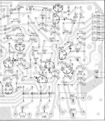
Just to make sure; disconnect the 5 pin plug A42 then solder the audio signal lead to the right of 2409, have posted an image showing this part?
Is this as far forward as we can test this time, as it would boost morale to hear full sound?
Is this as far forward as we can test this time, as it would boost morale to hear full sound?
Attachments
I don’t know what you can make of this 😕
I hear a buzz/hum after switching on the power from the bass speaker only, not very loud, it is there all the time.
The music sound on equal balanced setting is a bit better, though not as good as the other speaker. Turning the sensitive control makes no difference 😕.
I hear a buzz/hum after switching on the power from the bass speaker only, not very loud, it is there all the time.
The music sound on equal balanced setting is a bit better, though not as good as the other speaker. Turning the sensitive control makes no difference 😕.
The hum/buzz is most probably due to a ground loop because the ground point I told you to connect too (junction of the 3300uf caps 2243 and 2247) isn't 'pure' but it is a known good reference point. No worries over that at this stage.
So you have sound. This is good isn't it... we've not had audio like this from the unit before.
Connected as it is with the audio direct into cap 2409 means that none of the controls/switches on the speaker are in the loop. They won't work. That's the whole point of doing this, to determine whether the problem is before or after this point.
So how is the audio with regard to achievable volume ? That's the big question 🙂 Is it all present and correct ? All three speakers working ? I would guess (and this is only a guess) that it will appear around 60 or 70% as loud as the other. In other words if the main preamp volume is on 10 o'clock for the good speaker, you would need 2 o'clock to get the same overall level. That's just a guess though.
And it will sound very different to the other speaker at this stage because none of the filters and response correction is in circuit)
Nothing more can be learnt from this hum, being only on the bass speaker 
Don't forget my last post gives the relevant information; yes I would agree quote “60 – 70% as loud as the other” and yes quote “And it will sound very different to the other speaker at this stage because none of the filters and response correction is in circuit”.
A filter not working could explain a reduction of amplification
I don't think the hum will tell us much because its cause is simply us using what is technically 'a non clean ground'. I picked that point deliberately though, so as to rule out any breaks or high resistance paths in the grounds that spread off from there.
So taking the result of the audio being 60-70% the level of the other speaker points to the problem being to the left of cap 2409 which is the point we are injecting the signal. As you say, a problem with one of the filter stages could be causing the lack of amplification.
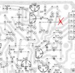
So we now have to inject the signal at a new point that includes more of the circuitry in the loop. The easiest place to do this electrically is at cap 2402.
So a check list to do this next step...
1/ You refit cap 2409.
2/ You lift cap 2402 at the end that goes to the emitter of transistor 6400.
3/ You connect the signal to this free end of the cap 2402. (The ground of the lead stays where it is on the 3300uf caps).
Doing those three steps now includes the filter network on board C and the filter around 6401 in the loop as outlined by the red box.
So taking the result of the audio being 60-70% the level of the other speaker points to the problem being to the left of cap 2409 which is the point we are injecting the signal. As you say, a problem with one of the filter stages could be causing the lack of amplification.
So we now have to inject the signal at a new point that includes more of the circuitry in the loop. The easiest place to do this electrically is at cap 2402.
So a check list to do this next step...
1/ You refit cap 2409.
2/ You lift cap 2402 at the end that goes to the emitter of transistor 6400.
3/ You connect the signal to this free end of the cap 2402. (The ground of the lead stays where it is on the 3300uf caps).
Doing those three steps now includes the filter network on board C and the filter around 6401 in the loop as outlined by the red box.
Attachments
With the balanced control set unaltered (equal) it is slightly improved from the last test, the sound is getting louder.
Only have to set the balance control over a ¼ now to achieve equal balance at the start/beginning it was 7/8
Only have to set the balance control over a ¼ now to achieve equal balance at the start/beginning it was 7/8
So its looking good 🙂 excellent.
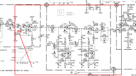
I'll have more time later... but what we do next is simply inject the signal into cap 2401. That means refitting 2402 and this time lifting 2401, the end that goes to 3404. You then inject the signal into the free end of the cap 2401.
That should sound similar to as you have now but this time the sensitivity control (half of it) is in the loop and so depending how you set it, it will affect the level.
More time later if you get stuck.
Even better; this is with the sensitive control full on pre-amp, the balanced control is set equal its very good 
Then turning the sensitive control over to speaker amp (I would expect more amplification) we are back to the fault at this point, loss of amplification/sound
Then turning the sensitive control over to speaker amp (I would expect more amplification) we are back to the fault at this point, loss of amplification/sound
This is all sounding very promising 🙂 So with the signal direct into cap 2401 its all pretty good and normal. Good stuff 
Now I have to try and convince you that with the sensitivity control over to 'speaker amp' it will go quiet. That's normal and as it should be. With it turned the other way, to 'pre-amp' as it is now, then it should be normal full volume.
So let us follow this through to some meaningful conclusion. We are now going to inject the signal directly onto point C402. So refit cap 2401 and transfer the signal wire to C402.
I would expect the result to be fairly similar to the previous test.
One step at a time now... see how it behaves with the signal direct onto C402
---------------------------------------------------------------------
Let me try and explain the sensitivity control. The speaker can accept a feed from a preamplifier (this is how you use it) or it can accept a feed from a power amplifier. The difference is in the applied signal level. The preamplifier puts out around 1 volt of signal as a maximum whereas a power amplifier puts out as much as 20 to 30 volts or even more in some cases. So the sensitivity control allows the option of reducing that 20 to 30 volts of signal down to a more manageable level of around a 1 volt that the speaker can work with. In other words it reduces the high level signal voltage from a power amplifier down to something equal to the level you get from your preamp.
- Status
- Not open for further replies.
- Home
- Amplifiers
- Chip Amps
- Philips 22AH587 replica modules