Yes you need C402 coupled up. I know we suspected the readings were odd from the pot but its also drawn a little oddly, as if it could be a special part.
Couple C402 up and see if the audio is back.
(its difficult keeping tabs on what we have connected and disconnected without visually seeing the unit and being reminded of it all)
Couple C402 up and see if the audio is back.
(its difficult keeping tabs on what we have connected and disconnected without visually seeing the unit and being reminded of it all)
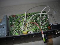
Have submitted photo showing the flying leads, sorry the focus is a bit out, you can still see. The attached PDF shows and gives this information, I need to know about the flying lead from c402 see the PDF. It is quite a tight fit when refitting the back leaving little room to add components, hence having to pack them to the inside of the board 😕
Attachments
Just to recap, when you had audio working in the previous test it was with a lead from C402 direct to 2426. And it worked.
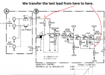
All you do now is transfer the test lead from C402 to your point 'B' on the pdf. That point is the emitter of transistor 6401. As you have the extra cap still in the test lead it can remain.
Just make sure that all parts in this box (B) are fitted.
All you do now is transfer the test lead from C402 to your point 'B' on the pdf. That point is the emitter of transistor 6401. As you have the extra cap still in the test lead it can remain.
Just make sure that all parts in this box (B) are fitted.
Attachments
I had the flying leads fitted to lower connection of 2426 leading to 3460, the other lead connected to c402, with c2426 fitted within the flying lead, and it worked.
Please confirm
Fit a flying lead from c402 D to B does it need a component fitting on this lead?
Quote “Just make sure that all parts in this box (B) are fitted” are you saying replace 3403 and 3406? This would just leave 2426 and 2409 removed.
Suggestion; if we could fit all back together as it was then totally bypass the Tandem Potentiometer 3401/3400 could this be more simpler and save time, to prove the fault?
Last edited:
Yes, replace 3403 and 3406. 2429 and 2409 stay removed for now. The test lead should be in the same place on 2426 as in the previous test when it all worked.
We could bypass the control now but I just feel we need to be logical and also not run the risk of anything going amiss or being missed. We have it in a state that works. Lets not risk confusing things 🙂
So it will either work or not at this next stage and that can only be either the control or that two transistor front end.
I won't be around much tomorrow so here's the plan......
You try it as we have discussed.
If it works then the fault is somewhere in the 'middle circuitry' and we would simply progress moving the test lead down the line as it were until we found the problem stage.
If it doesn't work then we know for sure the problem is between C402 and where we have connected the test lead. If we are at this point then shorting the pot out is the next step. To do that simply link the pins marked 1 and 2 on the pot. So that's the middle leg and the leg that goes to cap 2401.
If it still didn't work then the problem has to be in that transistor front end. We would know that for sure at this point because we have proved it already works if the test lead were transferred back to C402.
Was the volume a lot lower (like only 5 or 10% of the previous level) or just noticeably lower (say only 50 or 60% of previous level). I know its very difficult making educated guesses on levels.
I don't really think there is a lack of signal tbh.
I don't really think there is a lack of signal tbh.
Yes it was very noticeable down compared to the other speaker, weren't we expecting it to be as loud as the other speaker?
I would have thought it would have 'sounded' pretty similar even though the level after that stage is a little lower.
That said, it still works... we have signal... whereas with it in its original state it did not. So I think we need to move on and jump to the output of the next stage.
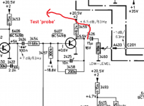
Your test lead is currently on the emitter of 6401. Simply transfer it from there and connect it to the emitter of 6106. You should still have audio.
That said, it still works... we have signal... whereas with it in its original state it did not. So I think we need to move on and jump to the output of the next stage.
Your test lead is currently on the emitter of 6401. Simply transfer it from there and connect it to the emitter of 6106. You should still have audio.
Attachments
That said, it still works... we have signal... whereas with it in its original state it did not. So I think we need to move on and jump to the output of the next stage.
In its original state it was working but with little sound, see posts 2 and 4.
Please review and reconfirm the next step.
Next step is as in the picture above and is just to transfer the test lead from 6401 to 6106... or have you done that ?
How does the level compare in these last tests compared to the level in posts 2 and 4 ?
How does the level compare in these last tests compared to the level in posts 2 and 4 ?
Mooly; working on this unit has now become depressing for me; my enthusiasm is now at a low, I am sorry to say, and I have lost my confidence in you as well.
I am willing to make one more test and that is after putting back the unit into its original state i.e. refit all the removed components.
Then make a simple bypass of the Tandem Potentiometer 3401/3400 and the Potentiometer 3460 this is the test.
If you are willing to help with this; please give instructions, if not then I say thank you for your help and I will just use the unit as it is in this state.
I'm sorry to hear you feel like that as I've tried to spell every step of the test procedure out down to the last detail for you.
To link the control out is easy if you never intend to use the high level input option. Simple remove the control (as that removes any possibility of there being anything internally faulty still causing an issue if it were left in place) and link points 5 and 6 for the first gang and points 1 and 2 for the second. Then make sure any of the removed components are refitted.
Then set the bass preset level control back to its original position by using the resistance value you measured earlier.
Thank you; I am going to leave the Tandem Potentiometer installed still and proceed to link 1 and 2 and then 5 and 6.
Potentiometer 3460 is it link bottom left to wiper centre 😕
Potentiometer 3460 is it link bottom left to wiper centre 😕
It sounded like you just wanted to put it all back together to its original state. 3460 is the bass level preset. Nothing gets linked on that, its just gets reset back to its original setting.
Would it be favourable to fit a resistor between link 5 and 6 to make up for the (assumed) shortfall, if so I would have to see what I have available; see post 88 gives these test results (there is a Z Z it should of been Y Z) 😕
Last edited:
Read the last bit first.
I don't think you need fit a resistor tbh.
This dual control is the only item with a question mark over it. Its drawn unconventionally as if it could be a special part and the function of the gang 3401 is unclear in conventional terms.
And I know you're not convinced 😉 so lets try and explain it in easy terms. Then you will understand the logic of it.
1/ Gang 3400 is totally conventional and wired as a normal volume control. You get maximum volume when '1' and '2' are effectively shorted which is when the control is at full. At minimum volume (2 and 3 are shorted now) there is always the 10k resistor 3405 in circuit. That means on minimum volume there is still some audio present. It doesn't fully remove the signal. Its all 100% conventional, a resistive divider. Ohms law.
2/ Gang 3401 can only do one of to things. We'll just consider the extreme case of it being a switch rather than a progressive control. That gang is drawn unconventionally.
So what can it so ? It can only add to the value of the resistor feeding it. That's 3403.
So what does all that mean is simple terms... it means that 3401 is intrinsically linked and dependent on the preamp feeding it as to whether it has any effect at all. If the source feeding the speaker has a low output impedance (meaning it can maintain its output into a low resistive load) then that gang would have no effect. So it relies on your preamp having a high output impedance.
Example. If the preamp has a 1k output impedance and you load it with 1k then the signal voltage drops by half, its just ohms law, a resistive divider.
So to prove beyond doubt whether the pot is good or not, all you really need do is short 1 and 2. That applies maximum signal to the amplifier stages, however if the pot is faulty/shorted/intermittent or whatever internally then you may well need to remove the pot and just link 1 and 2 on the PCB. That proves conclusively whether the pot is at fault.
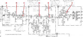
Another thought to make it easier to understand and fault find on is this which will give you something to work to without keep needing to ask each step of the way 🙂 The audio has a straightforward progression from left to right, yes the levels at each point vary somewhat but at no point should it suddenly drop out.
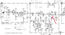
If you keep the polarity of cap 2426 as it is on the diagram then it will be OK for all the test points. Refit cap 2109 before you start.
You have rigged the bass amp up with a wire that can be used to probe the signal along its path as shown here. We know that works as you mentioned having loud audio in a previous test. Preset 3460 acts as the volume control in conjunction with the main level control.
The audio should be present at all these points marked A through to F. All you need do is work through and see if the signal 'disappears' at any point.
Attachments
Thank you for your detailed explanation on the sensitive control audio input and thank you for your latest point to test.
The set up: Refitted all components and linked 1 and 2 and then 5 and 6 together.
Test Results;
1. Music is coming through all 3 speakers, the sound level in comparison with the other speaker is still the same, have to turn the balance say 7/8 over to this speaker then its balanced well, the sound is quite good, I have to turn up the volume quite a way to make up for this.
2. Fitting the above links has not made any improvement, so I am going to remove them; I think it has now been proved the sensitive control is good.
3. Turning the sensitive control from full on speaker-amp to pre-amp the sound is slightly higher and a little clearer, (less muffled) whether this is still the case after removing the above links, is to be seen.
4. Something has gone down in value; resulting a loss of amplification, have replaced all the Blue Electrolytic Capacitors which proved essential, the issue is still the same?
5. These probably don’t make any difference; 3460 Trimming Potentiometer 10kΩ resistor is down it reads 8.13kΩ. and the one I smoked 3509 Fusible Resistor, 180Ω is replaced with a 100Ω?
6. Whilst board C was out I have checked all the voltages that are shown on the drawings that I usually post; none were far off, testing 6104 b made me jump, I got a big buzz.
7. Everything is working; yet there is a deficiency in amplification?
8. Do you think; a dropout could just be the cause of this, we have done buzz tests which were sussesfull?
- Status
- Not open for further replies.
- Home
- Amplifiers
- Chip Amps
- Philips 22AH587 replica modules