Lets go through your points...
1/ This is showing that all three power amps (one for each speaker) are working and behaving the same for the applied signal. So the lack of gain is common to all three.
I'm going to ask a crazy question now because you say I have to turn up the volume quite a way to make up for this.
Saying 'quite a way' only means something to you by visual reference to how you normally set things and so only you know by looking at the visual position of the controls how low in volume this speaker really is. Have to ask therefore... is there any possibility that this speaker is in fact OK, and that its the other that is exhibiting to much gain ? Strange question I know.
2/ Essentially yes, it proves the control good. The only question mark could be if the control had some weird/bizarre internal short that was shunting the signal. Never had a control fail that way... but nothing is impossible. The only way to prove that would be by removing it.
3/ ?
4/ Has the gain dropped ? Well we know all three power amps behave correctly (because the sound you hear is balanced) which means any lack of gain would be in the common stages before these.
This is what we have been trying to prove all along.
This is really really important if you can follow this. If you look at the circuit you will see various levels marked such as 0db/10kHz or -6.5db/63Hz and so on. This tells us that all the circuitry up to the power amps is essentially 'unity gain' (give or take), which means a voltage gain of 1. In other words what is applied at the input isn't amplified at all by all the small signal stages. Its the power amps (which we know are OK, and you wouldn't get all three faulty anyway) which provide all the voltage gain. The other stages just manipulate the overall response... the filters.
If you look at the wiper of the preset 3460 its marked as -1db/63Hz. That means that what appears at the input appears here virtually the same voltage wise. It is not amplified up to this point.
5/ No problem at all with the preset value.
R3509. As long as the voltage coming out of the regulator is OK then all is well. That means having approximately plus 20 volts on the 68 ohm, R3512
6/ Buzzing the base of 6104 introduces lots of hum and noise into the signal chain... which is good... its shows its getting through.
7/ 🙂
8/ Dropout ? Do you mean a break somewhere in the continuity of the signal path ? We've linked everything out.
Elaborating on my sections;
1. “I have to turn up the volume quite a way to make up for this” This is because the good speaker loses volume especially after turn the balance say 7/8 over (that’s a long way) to the other speaker to balance the sound level equal, to each speaker otherwise you only hear from one speaker, so you end up with low volume, hence you have to turn the volume up to hear.
2. If you aren’t sure; can we not bypass from c402 which would be simpler? Any issue with the ground being deficient?
3. The volume should decrease when turning the sensitive control to pre-amp not increase and the quality should be there either way when you turn this.
4. Agreed we should check this, but how, my meter as shown in post 11 Amazon link, gives tests for;
Frequency:
0~ 20KHz
0~ 10MHz ±(0.5% +2)
Duty Cycle:5%~ 95% ±(2% +2).
5. Good.
6. Well it certainly put life into me.
7. I think it is becoming clearer to us the problem area.
8. I meant as in your last proposal.
I think you are wrong about point 3. According to the user manual, the volume should increase when turned to "pre amp".
I know asking if the other speaker could have been at fault probably seemed strange but had to ask 🙂
Your meter... Fluke 73. The specs for that show its capable of AC voltage measurement with a 1mv resolution. It would have to be able to read voltages in the 0.5 to say 2 volt range with moderate resolution. 1mv resolution would be great, many meters would just show jumps of 0.1 volt or even 1 volt. If the meter is up to the job then I have an idea...
Would you be able to play a test tone on your system ? It would involve either burning an MP3 file to a CDR/CDRW (all CD players should play CDR, not all will cope with CDRW) or putting it on an MP3 player or similar and plugging that into one of the inputs on the amp to use as a source. That would hopefully enable a direct measurement of the signal level through the circuit. It would be a tone of around 400Hz at relatively high level. You could then trace the AC signal through the amp and see what's going on. So that things don't get noisy you would turn down/off the good speaker and we would turn the three level presets right down on the faulty one. That would allow you to trace the signal right up to the power amp stages.
The test would work like this. You would get the tone playing and then measure the level at C402. We would then measure the level through the circuit at the key points.
The MP3 should be no problem as I could make the file with Audacity and attach it as an MP3 to this thread.
Yes, Mark is correct on the sensitivity thing. The most sensitive setting is for using the preamp. The least sensitive is when you want to feed it from a high level input such as from another power amplifier output.
There is information in section 3 which seems to be misinterpreted, but by whom? this is section 3 in full.
Turning the sensitive control from full on speaker-amp to pre-amp the sound is slightly higher and a little clearer, (less muffled) whether this is still the case after removing the above links, is to be seen.
Below elaborating on this section.
The volume should decrease when turning the sensitive control to pre-amp (and this is because you are leaving the speaker-amp and coming on to the pre-amp, the pre-amp is just a small amp) not increase and the quality should be there either way when you turn this. END.
I take it the meter that measures frequency is not up to the job; I was hoping it would be and finding the results would be simple. We have done our best so far to find the fault of the issue; my time and patience is at an end now.
I need to finding a replacement for 3509 a Fusible Resistor, metal film 180Ω x 0.25 watt is proving difficult; I have choices of fitting; a none fusible type, or fusible types a 100R 5%, 0.5W or a 220R 5%, 0.5W please advise.
180 ohm carbon quarter or half watt is OK. If you can't get that then I'd go one lower and opt for 150 ohm. You can always make the value up with a series chain.
Having a meter that measures frequency is a bonus... but not related to being able to measure AC voltages. If the Fluke has a resolution of 1mv then its more than up to the job.
The sensitivity control is just an attenuator. You need the full signal applied (maximum gain if you prefer) when using the preamp as a source. When using a speaker feed as a source there is masses of voltage and so you attenuate it with the control before applying it to the circuitry.
I can do you an MP3 file that you can use at your leisure to see if that shows any sudden loss of signal. Nothing lost... just say if you want it.
The only choice I have come across will be a none fusible type with the same specifications for the 3509. I will make that do thanks for your help.
Fusible resistors are a pain to get hold of tbh. Philips used to use them like they were going out of fashion.
They are used because when they do fail (due to say an overload or short) they do so silently. A carbon resistor might smell and smoke (which frightens the customer) even though there is no real risk.
They are used because when they do fail (due to say an overload or short) they do so silently. A carbon resistor might smell and smoke (which frightens the customer) even though there is no real risk.
I thought to myself as I am giving up on this; surely there must be something that has not been checked that is available in the service manual and yes no voltage readings have been checked on board B there are quite a few incorrect; this could be the issue, see attachment PDF; Board B voltage reading 14March15.
Attachments
OK, lets go through them and see.
6216... is what is called a 'vbe multiplier' and it sets the bias in the output stage of that (treble) amplifier. The voltage will be variable between different units due to differing transistor characteristics and also dependent on the preset setting on its base (don't alter it). So no problem.
(and looking at the circuit in that area (on my copy) seem to show an error. Above 6216 is a 1.25 amp AT fuse marked '1205'. It wont just feed into that 1.5k resistor, other things will feed off from it)
6211 and 6213... are in parallel. It sounds a long way in error but looking at the circuit it sounds reasonable.
6225... a perfect example 🙂 The manual shows + 0.3 volts. This is a 'Darlington' transistor (essentially "two connected as one" so that the output of one feeds the other). It makes one super high gain device. Each base/emitter junction is biased at around 0.6 volts. That's a number that's cast in stone for any silicon device due to the physics involved in the materials used. So that means the emitter should be at around - 0.9 volts. The manual correctly shows 0 volts (the speaker feed). The 2.7 ohm emitter resistors drop a minisule amount and can be discounted (although the manual correctly shows 35 millivolts dropped across these).
So your measured 1.2 volts is what would be expected.
6226... as above. The proof the marked value is incorrect is that 0.3 volts and -0.2 volts is total value 0.5 volts between the two bases of those output transistors. Not enough. You need at least 2.4 volts total (four base emitter junctions in series at 0.6 volt each).
And your measurements added together give... 2.4 volts... exactly as the theory predicts.
6229 to 6232... these are all part of the relay driver and automatic detection of audio circuitry. There is also the DC offset protection feeding into this chain. What I would say here is that as long as the relay is closing correctly when there is audio and opening after a short period of silence then there isn't a problem. They are not in the audio path. They are just drivers and so on for the relay.
6234 and 6235... as above. These are DC offset protection. If the relay operates correctly then no problems here. If the relay wasn't closing there would be no audio from any of the speakers.
6215... vbe multiplier as covered in the other amp above.
6214... looks OK.
6217... last one... and the only that doesn't seem quite correct (don't get your hopes up though).
-1.2 volts on C and E means that there is no voltage across those points. Now its that voltage differential that biases the output transistors and we would expect around 2.4 volts or so here. That magic number. Worth rechecking for curiosity and certainly something to look at if/when its all working. Low bias on its own wont alter the gain of the stage or anything like that. All it will do is cause an increase in distortion (crossover distortion).
So one to recheck and ultimately see why its reading as it is.
Its good to go through them all though.
(A test tone and measuring the AC level from start to finish through the amp might just help resolve this because all we have done to date hasn't uncovered anything amiss. You have nothing to lose... if your meter can measure the AC values which will be around 1 volt or less then it could be a winner. There is no isolating of things or anything like that. Its straightforward measurement and seeing if the signal level is as expected or not)
Thank you Mooly; for going through all of that; I knew it would be quite simple for you to understand (and that could be set in stone as well) I think you are asking me if I have a meter that produces a tone when testing AC; well my new meter might, if you kindly would look, see 11, amazon, I will also have a look at the manual on Monday 🙂
I still have board B to fully test for voltages. I had the other board marked D and thought it was B anyhow I know what it looks like?
So I am hoping it is good news and it would be just a case of testing a component 🙂
I still have board B to fully test for voltages. I had the other board marked D and thought it was B anyhow I know what it looks like?
So I am hoping it is good news and it would be just a case of testing a component 🙂
The test tone is something I would attach to these posts, just a quick MP3 download. You would then either burn it to a CDR using media player in Windows or just load it onto an MP3 player and connect that as an input to your preamp.
I'll do that anyway (probably tomorrow)
I'll have a look at your link to the meter in the meanwhile. For some reason I thought you had a Fluke 73... lol, don't know where I've got that from.
I'll do that anyway (probably tomorrow)
I'll have a look at your link to the meter in the meanwhile. For some reason I thought you had a Fluke 73... lol, don't know where I've got that from.
Here is a 440Hz pure sine test tone as an MP3 file. It plays for 10 minutes and fades in and out at beginning and end. Treat it just like a music file and either burn to CDR or put it on an MP3 player so that you can use that as a source.
https://www.dropbox.com/s/ase1f3xyx1pogli/440Hz Tone.mp3?dl=0
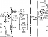
Your meter looks OK as it lists both a 200mv and 2 volt AC voltage range. How the meter reacts to an AC voltage superimposed on a DC value is an unknown and so I would advise just having a small capacitor in series with the red meter lead to block any DC. Cap 2109 is the obvious choice to use because the switch marked 'Side to wall' shorts this cap out anyway if set to the position shown here.
https://www.dropbox.com/s/ase1f3xyx1pogli/440Hz Tone.mp3?dl=0
Your meter looks OK as it lists both a 200mv and 2 volt AC voltage range. How the meter reacts to an AC voltage superimposed on a DC value is an unknown and so I would advise just having a small capacitor in series with the red meter lead to block any DC. Cap 2109 is the obvious choice to use because the switch marked 'Side to wall' shorts this cap out anyway if set to the position shown here.
Attachments
password-wall.... 🙁Here is a 440Hz pure sine test tone as an MP3 file. It plays for 10 minutes and fades in and out at beginning and end. Treat it just like a music file and either burn to CDR or put it on an MP3 player so that you can use that as a source.
https://www.dropbox.com/s/ase1f3xyx1pogli/440Hz%20Tone.mp3?dl=0
Your meter looks OK as it lists both a 200mv and 2 volt AC voltage range. How the meter reacts to an AC voltage superimposed on a DC value is an unknown and so I would advise just having a small capacitor in series with the red meter lead to block any DC. Cap 2109 is the obvious choice to use because the switch marked 'Side to wall' shorts this cap out anyway if set to the position shown here.
I hate the cloud!
password-wall.... 🙁
I hate the cloud!
Don't understand 🙂 I'm on a pc now that has no knowledge of Dropbox or my account with Dropbox and it opens just fine.
Attachments


- Status
- Not open for further replies.
- Home
- Amplifiers
- Chip Amps
- Philips 22AH587 replica modules