
Pffft..
We got a seven foot circular rosewood dining room table. Except ours is in much better shape than this (also, our has the wooden legs, not the chrome version).
https://www.etsy.com/uk/listing/132...ble&ref=sr_gallery-1-4&organic_search_click=1
We've sat as many as 12 people around it for dinner! King
Over the years we've looked for a large enough lazy susan for it... but short of stealing one from a Chinese restaurant, we have no clue... I thought of doing it myself, but then finding a bearing base of a large enough size is almost impossible.
Last edited:
The question isn’t will the two-chassis be better, it of course will, but instead will the one-chassis be quiet enough.
That’s what I’m testing.
Will the two chassis have a removable cable so we can swap cables? Can we use Nordost Silver Blue Heaven Reference Signature Balanced cables?
We may have invented a new cable niche... Low Impedance Balanced Power Supply cables.
Regarding the use of Burson opamps:
They only recommend the V6 for MM cartridge. I assume it is because of the noise figure?
As far as I can see they don't specify noise in their datasheet?
https://drive.google.com/file/d/1JyV88oA-33QHSHbGYF16A3FRW1mDRV1N/view
Thanks for the info. I think I'll send them an email about it.
I'm running V6 classics/vivids in my Burson Play DAC...
It is a jfet input opamp 🙂They only recommend the V6 for MM cartridge.
We got a seven foot circular
how many OPs you can lay on that table, to test them

Depends.... do you want my wife to kick me out of the house?
Our dining room table has a nice, thick cover. So, she lets me use if for wiring up stuff, she even didn't say much when I put the F5 on it for a "burn in test" and the darn thing smoked!
But I think there are limits to her patience which I do not want to find.
Our dining room table has a nice, thick cover. So, she lets me use if for wiring up stuff, she even didn't say much when I put the F5 on it for a "burn in test" and the darn thing smoked!
But I think there are limits to her patience which I do not want to find.

In case anyone is interested or paying attention, the difference between ZTX450 and ZTX851 in the cap multiplier is negligible.
Kits will ship (well, the first batch, anyway…) with ZTX457 for multiplier and ZTX851 for the cascode. This puts the strengths of each transistor in the position where it will be more ideal for the job, and more kits will ship with the (currently) unobtainable 851s.
Well MC have very little(low) source impedance, and bjt's are much more suited for it as they are lower V noise, and higher I noise, comparing to jfet's which are the opposite.Well, back to square one then? 😛
Perhaps ZXTN2018FTA?Kits will ship (well, the first batch, anyway…) with ZTX457 for multiplier and ZTX851 for the cascode. This puts the strengths of each transistor in the position where it will be more ideal for the job, and more kits will ship with the (currently) unobtainable 851s.
Ooooh! That looks nice, but the PCB doesn’t have SMD pads on that position, so substitutes would be preferably TO-92 and EBC. Like Wayne’s choice of KSC1008YBU.
Ment it as a future revision 😁 as with input jfets, dual footprint. I belive it is a smd replacement for ztx851.
Well MC have very little(low) source impedance, and bjt's are much more suited for it as they are lower V noise, and higher I noise, comparing to jfet's which are the opposite.
I'm using a Grado moving iron (Master II), which according to the factory doesn't need a capacitive load, just a nice 47K impedance and at least 55db gain ( it's a 1.0 mV output).
So, maybe the Grado will work with the jfet?
Why is everybody worried about bipolar vs. JFETs on the opamp? The cartridge only sees the parallel discrete Toshiba Jfets, not the input of the opamp. Opamp construction totally doesn't matter for this metric.
🙂
🙂
Strictly speaking the Vendetta was a four chassis solution.The Vendetta Research SCP-2 moving coil preamp (1988) was a two chassis solution.
Hello All,
In the little hours this morning I measured The IDSS of 60 2SK170 GR and did a couple of calculations on a post-it note pad.
R4, R5, R6, R7 and R8 are all 10R resistors. All 4 JFETS; Q1, Q2, Q3, and Q4 all source current through resistor R8. If each JFET sources 0.003 Amps then R8 sees 0.012 Amps through current and 0.120 Volts drop across the resistor. For R4, R5, R6, R7 and R8 each resistor will see 0.003 Amps through 10R or an additional Voltage drop of 0.03 Volts for a total Voltage drop across the source resistors of 0.123 of each JFET.
I tested each JFET for IDSS and Current with 50R of Source resistance. (Per the data sheet the test voltage was 10 Volts DC).
An interesting thing (to me) happened; for the most part the current measurement with a 50R source resistor was, +/- a RCH, 50% of the IDSS. (Red Curley Hair or ~ +/- 1%).
For the short version; a 2SK170 BL with an IDSS of 8ma will draw near 4ma in this Pearl 3 circuit.
Thanks DT
Yes, I know that generally PSU in its own chassis is a better solution. I use that for many of my amps. E.g. the Lazy Singing Bush where PSU's are placed 0.5 - 1m away from amps to avoid magnetic fields. Also VFET Kit amp uses this, ACA etc.The question isn’t will the two-chassis be better, it of course will, but instead will the one-chassis be quiet enough.
That’s what I’m testing.
When I looked at the two chassis solution I had in my mind that many people will probably stack them. Doing that and if chassis are aluminium rather than steel the PSU magnetic field may come closer to the P3 boards than in the one chassis solution. Also if the splitter in the one chassis solution is steel and you cover the PSU part with e.g. mu-metal I was thinking that maybe the one chassis solution could be as good as a two chassis solution (also that the PSU in such an amp has much less fields but then the circuit is a lot more sensitive so probably "same same" compared to the power amps).
I will probably go with a two chassis solution and ensure the PSU chassis is at a good distance from the P3 chassis. Unless some measurement was made that showed that the two solutions were equally quiet. It may also depend of how large the "one chassis" is 🙂 .....but the pictured is less than 1m wide 🙂
Is is a nice thing that the regulators are placed at the P3 board. Then longer wires to it is not that critical.
Hello PEARL 3 - builders,
very nice work from all!
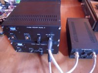
This is my chassis-solution I did some years ago with my PEARL 2 (3 chassis). I will do something similar with the PEARL 3.
Have fun with this project!
I wish you all a nice weekend
Dirk 🙂
very nice work from all!
This is my chassis-solution I did some years ago with my PEARL 2 (3 chassis). I will do something similar with the PEARL 3.
Have fun with this project!
I wish you all a nice weekend
Dirk 🙂
Attachments
Dirk, do you have more pix of your dip switch setup on your P2? Including internal pix?
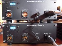
My Pearl 2 is a 2 box solution with adjustments on the back using knobs and a gain switch. I now know the settings of my carts, so the P3 will be a “set and forget” philosophy for me.
My Pearl 2 is a 2 box solution with adjustments on the back using knobs and a gain switch. I now know the settings of my carts, so the P3 will be a “set and forget” philosophy for me.
Attachments
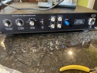
Hello Randy (i hope your name is right?),
I was also thinking about a rotary switch solution. Can be done very nicely from the frontpanel or from the backpanel - question of taste for me.
Rotary switches can be expensive...
I have used simple dip - switches and a small selfmade pcb. I have a paper note (anywhere), where I wrote down the R- and C- values and the values if you switch the Rs or Cs in parallel.
I will find it. Please, give me some time.
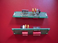
I have a foto of the prototypes (input R-/C-load) on protoboard.
Cheers
Dirk
I was also thinking about a rotary switch solution. Can be done very nicely from the frontpanel or from the backpanel - question of taste for me.
Rotary switches can be expensive...
I have used simple dip - switches and a small selfmade pcb. I have a paper note (anywhere), where I wrote down the R- and C- values and the values if you switch the Rs or Cs in parallel.
I will find it. Please, give me some time.
I have a foto of the prototypes (input R-/C-load) on protoboard.
Cheers
Dirk
Attachments
- Home
- Amplifiers
- Pass Labs
- Pearl 3 Burning Amp 2023