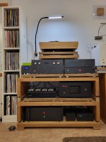
Finally my pearl3 is playing, thank you Wayhne, 6L6 and everyone involved in this great project.
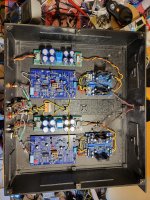
@ Boydk Thanks for the Jfets and I don't miss my defective Xono, you were right.
The case and parts of the power supply are from my Xono.
@ Boydk Thanks for the Jfets and I don't miss my defective Xono, you were right.
The case and parts of the power supply are from my Xono.