Rod wrote back to say, "...Sorry, but no PCBs are available for P166, as it's expected the selected circuit will be wired on Veroboard."I looked into Rod Elliott's Project 166 and have dispatched email to him since boards for that project do not appear in his store. I'll follow-up with what I find.
So...the H9KPXG it is. Mark - thanks for the circuit and the board!
Pardon me...
I've been through the thread looking for a "range" of possible switches, but still am not sure. I may have overlooked the answer...
Mark repeatedly stated that more or less any switch would work, as it's triggering low voltage... but, does a basic on-off switch do the trick too? (no 'impulse' of sorts needed to engage the unstart-process?)
Thank y'all!
The documentation in the first post leads me to believe that a non-momentary switch can be used, selected by a jumper on the PCB:
“The PCB user installs a shorting bar across pin header P6 when using a momentary switch on the front panel; this enables U1B. If there is no shorting bar across P6, U1B is disconnected and the non-momentary front panel switch controls On-Off behavior and timing.across pin header P6 when using a momentary switch on the front panel; this enables U1B. If there is no shorting bar across P6, U1B is disconnected and the non-momentary front panel switch controls On-Off behavior and timing.”
“The PCB user installs a shorting bar across pin header P6 when using a momentary switch on the front panel; this enables U1B. If there is no shorting bar across P6, U1B is disconnected and the non-momentary front panel switch controls On-Off behavior and timing.across pin header P6 when using a momentary switch on the front panel; this enables U1B. If there is no shorting bar across P6, U1B is disconnected and the non-momentary front panel switch controls On-Off behavior and timing.”
Toggle switch is ok. Rocker switch is ok. Slide switch is ok. Rotary switch is ok. Latching pushbutton switch is ok. Non-latching pushbutton switch is ok.
If the switch manufacturer's datasheet is unclear or unavailable, you can find out whether or not your switch is momentary, by deploying diyAudio's secret weapon: ingenuity. Use a pair of crocodile clip hookup wires to attach your switch's terminals to your DVM in continuity test ("beep") mode. Actuate the switch into position #1 and take your hand away. Does it beep continuously when your hand is removed? Or does it beep only when your hand is actuating the switch? Repeat the other way: actuate the switch into position #2 and take your hand away. Does it beep continuously when your hand is removed? Or does it beep only when your hand is actuating the switch?
Now you know whether your switch is momentary or not. Apply the post #1 instructions about pin header P6 {very helpfully repeated by Halauhula into post #743 above} and Bob's your uncle.
_
Attachments

( last sentence threw right back into my last binge-excess, for all mankind: „Hi Bob!“, and in the background, coincidentally, velvet underground‘s „I begin to see the light, woohoo!“ 🥳)
I onsider myself blessed, blissed, a wee tiny bit educated, and dare to conclude:
A switch is ok.
Thank you, Mark, thank you, Halauhula!
I onsider myself blessed, blissed, a wee tiny bit educated, and dare to conclude:
A switch is ok.
Thank you, Mark, thank you, Halauhula!
Last edited:
Hm. Houston I have a problem…
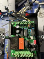
So I finally got my parts torgether, tightly built or prepared to be and mechanically tested, and so I started to power up the various stages, beginning with H9KPXG…
It seems to partially work, that is, there‘s no delay, the light-bulb-test is not satisfying:
When the rear switch is closed, the bulb immediately goes on, the ON-led is glowing.
Opening the front-switch (which should enable soft-turn-off) nothing changes: light-bulb and ON-led are on.
Opening the rear switch of course turns it off, and a nice and distictive relay-click is audible.
H9KPXG is configured for 240V (P1D-P2N, no jumpers, jumper at 2“ delay, no jumper at P6 („momentary option“)…
Anything plugged wrongly or a problem buried deeper?
Thank you
Attachments

I've never configured one for anything other than 120... so, this is just an observation vs. calling out what I think could be the issue.

Thank you @ItsAllInMyHead !
The sketches for the primary configuration (way back in the thread) for single primary says so:
P1D-P2N no jumper
(A dual primary would use P1 and P2 D/N and the jumper at 230…)
And the lightbulb goes on and nothing smokes…
The sketches for the primary configuration (way back in the thread) for single primary says so:
P1D-P2N no jumper
(A dual primary would use P1 and P2 D/N and the jumper at 230…)
And the lightbulb goes on and nothing smokes…
Attachments
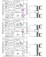
^ Very interesting. Based on the diagram, I'd have thought that the jumper was not needed with the single primary. I admit that I don't remember that diagram. 
You got it correct:
single primary 230V = no jumper
dual primaries = either 2 jumpers @ 115V or 1 jumper @ 230V
🙂
single primary 230V = no jumper
dual primaries = either 2 jumpers @ 115V or 1 jumper @ 230V
🙂
I would close the 'back-switch' while the 'front-switch' is in the off position.[...]
When the rear switch is closed, the bulb immediately goes on, the ON-led is glowing.
Opening the front-switch (which should enable soft-turn-off) nothing changes: light-bulb and ON-led are on.
[...]
I'm confident I tried this too, but will of course give it another shot...
After that, I might try a different switch just to see what happens...
After that, I might try a different switch just to see what happens...
It wont matter while using a momentary switch. But sins a toggle switch doesn't produce a positive going edge while switching it off, the D-flip flop has to be disengaged by pulling P6. R9 now becomes the data path and the circuit will, with some delay, follow the state of the toggle switch.I'm confident I tried this too, but will of course give it another shot...
After that, I might try a different switch just to see what happens...
Opening the front-switch (which should enable soft-turn-off) nothing changes: light-bulb and ON-led are on.
Are you sure that your switch is working correctly? Are you sure it is wired correctly? In looking at your photo I would think that the on position would have a connection to the top pin on the switch - which seems to have some heat shrink on it. In any case, do double check that switch with a meter!
I'd also be interested to understand why you are getting no delay with the 2 second option selected...
EDIT: Also, check out Mark's post here. Good information about troubleshooting. Yes, it refers to a momentary switch, but the probe suggestions are spot on.
Last edited:
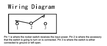
I did check the switch with dmm before installing it. it's either open or closed, according to the marking on the connected pins. I'd be using it according to this attached sketch... ( http://www.learningaboutelectronics.com/Articles/SPST-rocker-switch-wiring.php )
I'll check the various possibilities Mark pointed out. I hope it won't be dead stuff...
I'll check the various possibilities Mark pointed out. I hope it won't be dead stuff...
Attachments
I can‘t (cross my fingers), have to fiddle 🤦🏻♂️😁, thanks bhjazz!
(As I fell asleep yesterday, I thought maybe I should just remove it and run my new amp the firstwatt-way, with a CL-60, so I could have both a new amp and a jig to debug

…)
(As I fell asleep yesterday, I thought maybe I should just remove it and run my new amp the firstwatt-way, with a CL-60, so I could have both a new amp and a jig to debug
…)
Last edited:
- Home
- Amplifiers
- Power Supplies
- PCB: low voltage On-Off switch drives AC mains relay \ includes soft start .. H9KPXG