Interesting project, Mark. I've been searching for a way to use a low-voltage switch on my BA2018 build. And while my project doesn't really need the soft-start, it will be a welcome addition. I can now remove the big ol' power button from the rear panel design. Cool.

Mark, thank you for your effort!
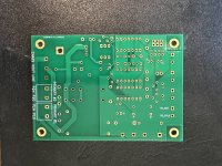
I have just built two modules, all good.
I have six spare PCBs (I have ordered 10 with intention to share here).
Manufacturing details:
Base Material: FR-4
PCB Thickness: 1.6
Surface Finish: ENIG
Gold Thickness: 1U"
Outer Copper Weight: 2 oz
I have paid about 6 Euro per PCB (boards, shipping and tax), shipping across EU is about 6 Euro (registered economy).
If anyone in EU would like to get such a PCB (6+6 Euro), PM me. Six boards to go.
Attachments

So after the initial power on the inrush current goes through ICL, time delay passes, and then relay contacts are closed to bypass ICL and connect the load to mains. My question is why there is no need for relay contacts protection like RC snubber? Would there still be an arc when relay bypasses ICL? Thanks
A vendor sells a fully assembled and tested soft start PCB similar to this one, currently priced $189 plus shipping. They consider VivaVee's observation (about H9KPXG) to be an important sales feature of their board too
The vendor's sales page says ...
Relay Saver Technology I: An electronic switch engages the soft start before the main power relay on power-up and disengages after the power relay on power-down. This minimizes the switching current and voltage across the relay contacts, thereby minimizing arcing and the associated contact wear and RF emissions.
("An electronic switch" on the sales page, is triac T1 on the H9KPXG schematic)
At the time that the relay contacts close, current is already flowing through the triac therefore the voltage across the relay contacts is almost zero, therefore no arcing.
The vendor's sales page says ...
Relay Saver Technology I: An electronic switch engages the soft start before the main power relay on power-up and disengages after the power relay on power-down. This minimizes the switching current and voltage across the relay contacts, thereby minimizing arcing and the associated contact wear and RF emissions.
("An electronic switch" on the sales page, is triac T1 on the H9KPXG schematic)
Got it, thanks 🙏
I’m curious, what is the power consumption for the board in idle and during operation, watt?
I’m curious, what is the power consumption for the board in idle and during operation, watt?
Hello to all!
I just finished soldering my H9KPXG, no testing was done yet.
I want to use it in my forthcoming project, the Holy Grail, and will cheat a little bit: I‘ll connect 2 PSUs (2x18V 150 VA, 72000 uF CRC) to it.
I was adised to place the fuses—1 per side—after the switch…
Does this apply here too?
(Mark‘s wiring diagram in post #2 indicates the switch being after the/part of the IEC…)
Many thanks! Apologies if this has been asked before, I‘m not yet through with the thread, but working on it.
myleftear:
Yup; I was advised by the esteemed Zen Mod to add fuses between an H9KPXG and two toroids in my dual mono F6 project (see post # 5498 at https://www.diyaudio.com/community/threads/pictures-of-your-diy-pass-amplifier.166784/page-275 ).
Regards,
Scott
Yup; I was advised by the esteemed Zen Mod to add fuses between an H9KPXG and two toroids in my dual mono F6 project (see post # 5498 at https://www.diyaudio.com/community/threads/pictures-of-your-diy-pass-amplifier.166784/page-275 ).
Regards,
Scott
Yes. "A vendor" does that. That board also includes several other attractive features that yours doesn't. It also comes with near-instant, personal support via email should you ever have trouble with it or questions about it.A vendor sells a fully assembled and tested soft start PCB similar to this one, currently priced $189 plus shipping.
Yep. That is indeed from the ISS product page: https://neurochrome.com/products/intelligent-soft-start.The vendor's sales page says ...
Relay Saver Technology I: An electronic switch engages the soft start before the main power relay on power-up and disengages after the power relay on power-down. This minimizes the switching current and voltage across the relay contacts, thereby minimizing arcing and the associated contact wear and RF emissions.
Tom
 me. hehe...)
I think that $189 is reasonable as the module from Neurochrome is already assembled: no need to spend time looking for and agonizing over appropriate part selections.Yes. "A vendor" does that. That board also includes several other attractive features that yours doesn't. It also comes with near-instant, personal support via email should you ever have trouble with it or questions about it.
Yep. That is indeed from the ISS product page: https://neurochrome.com/products/intelligent-soft-start.
Tom
May not satisfy those that want to DIY all the way, but having choices is good!! Mark’s board is excellent way to have. DIY experience and perhaps learn more about design-if only to understand that engineering is not a simple matter. Although to be fair, Neurochrome has a blog entry that goes into detail about design considerations for soft start. I think those interested in the subject should read it carefully.
Going back to Mark's H9KPXG...
I am building a Stasis with ZM's boards for 50V rails (thread `New Stasis front end'). There are many threads the Pass Labs subforum on PSU filter configurations; CRC, CLC, pi filters etc., the consensus would appear to be that CLC might be a good way to go. Something like 44mF - 10mH - 44mF using a Hammond 159ZJ choke in place of the typical parallel resistors. I'd also like to leverage the latest variant of the F5M power supply board which has places for 4 caps after the bridge rectifiers for each rail (so 8 in total; 4+ and 4-), and subsequently 4 separate RC cells; one for each rail and for each channel. I'd like to swap in four 159ZJ in place of the CL used on the F5m. So as to end up with 88mF - 10mH - 22mF on each channel/rail with the LC being four independent legs
https://www.diyaudio.com/community/threads/f5m-kit.408290/page-64#post-7663166
However, if I stick 22mF (63V DC rated) capacitors everywhere, then from the first post on this thread, I end up with an inrush charge of >250J (=0.5x12x0.022x50x50) which is beyond the capacity of the optional largest CL (which I have used in building this board).
I could perhaps use the shortest time delay and just use Mark's circuit to `take the initial bite' out of the inrush surge, but this doesn't appear (to me), to be optimal.
I could perhaps build a pair of boards and supply each channel with its own delay board, but this seems a bit `overkill' and not the most intellectually elegant solution.
Another option might be to add the chokes as planned but leave a CL in series with each choke. In this manner Mark's H9KPXG board would address the inrush associated with the first 8x 22mF caps and the high initial cold resistance of the CL would mitigate the impact of the additional 22mF sitting on each channel/rail (4 in total). A small amount of resistance in series with the choke may also assist with managing any tendency for the LC filter to ring. Something like NTC B57236S0229M000...
Does this seem a reasonable approach and/or are there better solutions - please educate me.
thanks
A few years back, Wayne Colburn drew the Forum's attention to the Ametherm "MegaSurge" line of inrush current limiter discs (product link) , which go up to 800 Joules (!wowzer!). I imagine one of those might be so physically large that you'd have to mount it off-PCB, and then make electrical connection using flywires. Once you visit Ametherm's products web page, take a look at their numerous other product lines, offering different sizes and Joule ratings.
Another approach, which appears in Douglas Self's power amp book, is to connect N>1 inrush current limiter discs in series (never in parallel). Two 50J discs in series give 100J of energy absorption for example.
Another approach, which appears in Douglas Self's power amp book, is to connect N>1 inrush current limiter discs in series (never in parallel). Two 50J discs in series give 100J of energy absorption for example.
Would the board’s copper survive such treatment? (Alternatively, the option of using 1 H9KPXG per channel would be another possibility?)
thanks Mark - I had completely overlooked the idea of putting more than one in series. I'll go look at these big puppies. I bought enough parts for several boards, so simplest may to be just put two in series. Thanks.
@mylefteary -I'd rather not build one delay board per channel though I have considered this. It's perhaps not the most elegant solution it might have some advantages in terms of potential troubleshooting etc.
@mylefteary -I'd rather not build one delay board per channel though I have considered this. It's perhaps not the most elegant solution it might have some advantages in terms of potential troubleshooting etc.
If I were going for a single CL then perhaps this looks like the right puppy
https://www.mouser.com/ProductDetail/Ametherm/MS35-20010?qs=PVyXUKBeRH1hG9TUGmmutg==
20ohms cold and 500Joules.
got some serious legs on that thing 2.5mm diameter! welding rods.
https://www.mouser.com/ProductDetail/Ametherm/MS35-20010?qs=PVyXUKBeRH1hG9TUGmmutg==
20ohms cold and 500Joules.
got some serious legs on that thing 2.5mm diameter! welding rods.


- Home
- Amplifiers
- Power Supplies
- PCB: low voltage On-Off switch drives AC mains relay \ includes soft start .. H9KPXG