Could i have your help with the AC/DC converter module 709-IRM02-5? I tried to order it from Mouser but they told me that this certain product is not provided to consumers. Does anyone know where else i can find this or what else i could replace it with?
^ Is that only for your country? I just ordered and received 6 of them from Mouser for this project. They are still showing as orderable and available in the USA.
When I switch my location to Greece in Mouser, I still show them as available and orderable, but perhaps I am missing something.
https://gr.mouser.com/ProductDetail/MEAN-WELL/IRM-02-5?qs=C9r8PV/%2BoWNou94IFFYO3A==
When I switch my location to Greece in Mouser, I still show them as available and orderable, but perhaps I am missing something.
https://gr.mouser.com/ProductDetail/MEAN-WELL/IRM-02-5?qs=C9r8PV/%2BoWNou94IFFYO3A==
@ItsAllInMyHead
once in the cart you get this message:
"Product only available to OEM/EMS customers and engineering companies. The product is not shipped to private individuals in the EU or UK."
@kosthsth
I used this instead
https://www.mouser.it/ProductDetail/RECOM-Power/RAC02E-05SK-277?qs=KUoIvG/9IlZMxwR8%2BdSt6A==

I am thinking about getting the board, but since I am using switching PSU from Connex electronics I don't think that I need the soft start feature.
I want to add power button to my build though.
Thinking about this guy here - 612-PV6FW40SS-331 by E-Switch.
Will the board presented in the first post be overkill for my needs?
I am not opposed to putting together something simple using small switching 5V PSU and relay to control on and off for the mains.
Thanks in advance for help.
Try ordering from Digikey. I've been told they're willing/able to sell to private individuals within the EU. Otherwise go to Mean Well directly and find their European distributor(s).
Tom
Tom
Hello everyone,
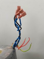
I'm in the process of setting up a soft start circuit and I want to double-check my toroidal transformer wiring. I've attached two pictures for reference. The label and the wires. I'm using two toroids in double mono configuration. I'm connecting the green/yellow wires of both toroids to the inlet Earth/Chassis. As for the 230 primaries, I'm connecting four red wires in parallel to P1D and P2N. I'm mostly unsure about the green/yellow wires. Is this the correct way to connect them to the inlet Earth/Chassis and both transformers with a soft start circuit? Thanks in advance!
I'm in the process of setting up a soft start circuit and I want to double-check my toroidal transformer wiring. I've attached two pictures for reference. The label and the wires. I'm using two toroids in double mono configuration. I'm connecting the green/yellow wires of both toroids to the inlet Earth/Chassis. As for the 230 primaries, I'm connecting four red wires in parallel to P1D and P2N. I'm mostly unsure about the green/yellow wires. Is this the correct way to connect them to the inlet Earth/Chassis and both transformers with a soft start circuit? Thanks in advance!
Attachments
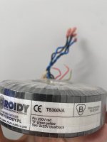
Solder a jumper in position 230V. Leave positions 115V in their virgin, unstuffed and unsoldered condition
Red wires of transformer_left connect to P1D and P2N
Red wires of transformer_right connect to P1D and P2N
Green/yellow wire of transformer_left connects to chassis earth
Green/yellow wire of transformer_right connects to chassis earth
Red wires of transformer_left connect to P1D and P2N
Red wires of transformer_right connect to P1D and P2N
Green/yellow wire of transformer_left connects to chassis earth
Green/yellow wire of transformer_right connects to chassis earth
I know this was designed for the purpose of a soft start for a power amp, but could it be used for any DAC or preamp project to use the anti vandal front switches? I know the need for a soft start is not there. Some of my projects will be using 2 or more transformers, would this be a problem connecting to the PCB? I could use terminal strips to make it work.
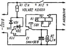
I don't see why not. You could leave out he the thermistor, relay and a couple of the logic gates. I didn't look closely, but it should work just fine as an on-off with anti-vandal front switch.
@wcwc
If your goal is to just use the anti vandal switches there are other diy circuits available to do so, such as the AMB epsilon 24 power switch driver circuit. It’s much more compact and does not have a soft start feature, but can be built with an optional relay (which can be sized appropriately) for low current circuits, such as DACs, preamps, etc….
I’ll have a few for sale in the future as I remove them from some of my older power amp builds and replace them since my older power amp builds didn’t have a thermistor (i.e. softstart) and they really should to ensure the longevity of the power transformer. My general recommendation has been that if the circuit (typically a power amp) requires 300VA or more, one should use a soft start to minimize the risk of having the primary short to the transformer core after several years of use.
Best,
Anand.
I thought I would ask before ordering. Does anyone have a spare PCB they would sell?
Cheers,
Soren
Cheers,
Soren
I see I'm too late to the party.
I also have a few spare boards and key parts. Just fyi going forward.
This board is the greatest thing since Swiss cheese. I use it in all my projects.
I also have a few spare boards and key parts. Just fyi going forward.
This board is the greatest thing since Swiss cheese. I use it in all my projects.
Hi mark, I had 10pcs pcb made in green 2oz. Which thermistor would you recommend for 600W toroid + 80.000 uF (125J or 250J)?
Thanks...
Thanks...
My H9KPXG arrives today. I'm using the DIY universal PSU in a dual mono. I've read all the posts in this thread and still want to double check how I wire this in. Attached is what I think I've learned. Does this look right?
Also I have this set as as dual fused. Is there a way to keep this and still use just just one H9KPXG-- like fusing the P1n and P2n wires?
Sorry in advance
 for such a boring, low level question, I just hate smoke, though
Also I have this set as as dual fused. Is there a way to keep this and still use just just one H9KPXG-- like fusing the P1n and P2n wires?
Sorry in advance
- Home
- Amplifiers
- Power Supplies
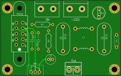
- PCB: low voltage On-Off switch drives AC mains relay \ includes soft start .. H9KPXG