I don't know,but now two channels are closed each other in measurements (R channel 3v3 on R5,L channel 3v2 on R5).Does lower gain suite you better?
Last edited:
ok thanks,are those c5,c6 22uf critical?
Can i use 47uf?
j1,j2 ?
Is tl071 ok for servo(just for the test period)?
During the test period i see that tl071 not perform well as offset comparator.Those caps are not critical, TL071 should be OK.
J1 and J2 is the position for the jumper(only in one position at a time. CFA or NGNFB).
Fitting this tl071,preamplifier output never come to zero d.c volt. This stay to 5mv after 30 seconds.
Fitting the LF411 ,after 30 seconds i see 0V d.c.
I don't know if this is a result of difference inverted and non inverted input for these i.c
During the test period i see that tl071 not perform well as offset comparator.
Fitting this tl071,preamplifier output never come to zero d.c volt. This stay to 5mv after 30 seconds.
Fitting the LF411 ,after 30 seconds i see 0V d.c.
I don't know if this is a result of difference inverted and non inverted input for these i.c
I thought that TL071 could be good for a DC servo as it is fet inputs op mp, but never used it for that. Maybe you just used a bad one, try another one.
No Damir, i have use two pairs each from different firm (national semiconductor . and motorola(on semiconductor),same things. 4mV Offset even after 1 hour.I thought that TL071 could be good for a DC servo as it is fet inputs op mp, but never used it for that. Maybe you just used a bad one, try another one.
LF411 give 0 mV after 30 seconds.
It's a matter of the part's offset voltage. The 411A is typically as low as 300uV, the 071 as high as 10mV depending on grade.No Damir, i have use two pairs each from different firm (national semiconductor . and motorola(on semiconductor),same things. 4mV Offset even after 1 hour.
LF411 give 0 mV after 30 seconds.
The 411s are laser trimmed I believe.
It's a matter of the part's offset voltage. The 411A is typically as low as 300uV, the 071 as high as 10mV depending on grade.
The 411s are laser trimmed I believe.
So, the solution is, use LF411 as is in the BOM.
Hi Damir,What your opinion about this arrangement
A potentiometer then a buffer(the kuartlotron)and finally the GainWire?
A potentiometer then a buffer(the kuartlotron)and finally the GainWire?
Hi Damir,What your opinion about this arrangement
A potentiometer then a buffer(the kuartlotron)and finally the GainWire?
The GainWire is a buffer too, no need for another buffer, only more distortion.
You can use higher ohm potentiometer then 10k (50k), I used 10k to get lower noise.
What is the kuartlotron?
That's Keantoken's error correcting buffer.
http://www.diyaudio.com/forums/anal...kens-simple-error-correction-superbuffer.html
http://www.diyaudio.com/forums/anal...kens-simple-error-correction-superbuffer.html
I used two mono potens. 25k log. because that is what i have in hand.The GainWire is a buffer too, no need for another buffer, only more distortion.
You can use higher ohm potentiometer then 10k (50k), I used 10k to get lower noise.
What is the kuartlotron?
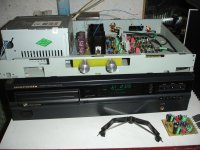
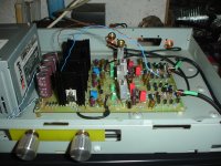
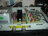
Mk2 as it now
Attachments
-
 DSC09368.JPG582.1 KB · Views: 546
 -
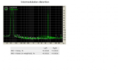 intermodulation.PNG30.6 KB · Views: 176
 -
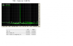 thd noise.PNG30.4 KB · Views: 166
 -
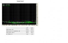 noise level.PNG29.9 KB · Views: 184
 -
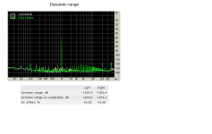 dynamic range.PNG28.3 KB · Views: 182
 -
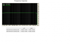 frec res.PNG22.9 KB · Views: 210
 -
 gainwire details.PNG61.7 KB · Views: 450
 -
 DSC09371.JPG584.8 KB · Views: 458
 -
 DSC09370.JPG542.4 KB · Views: 488
 -
 DSC09369.JPG620.3 KB · Views: 517
Last edited:
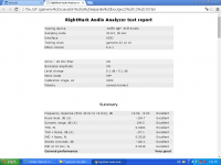
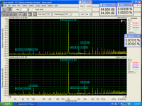
testing results using SpectraLAB
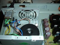
What was the load at the GW output when you were doing the measurements?
Thear isn`t any load than sound card line input impedanceWhat was the load at the GW output when you were doing the measurements?
Last edited:
Thear isn`t other load than sound card imput impedanceWhat was the load at the GW output when you were doing the measurements?
Thear isn`t other load than sound card imput impedance
There is always 10k resistor on the output.
There is always 10k resistor on the output.
Thank you both for reply. That's what I suspected. It would be good to see how GW measures when loaded with something like 50R.
Thank you both for reply. That's what I suspected. It would be good to see how GW measures when loaded with something like 50R.
For low impedance headphones is better suited this one with some changed values. http://www.diyaudio.com/forums/solid-state/235695-no-nfb-line-amp-gainwire-mk2-81.html#post4475027
There wrongly marked line and phone output on the schematic, it is just up side down.
- Status
- Not open for further replies.
- Home
- Amplifiers
- Solid State
- No NFB line amp (GainWire mk2)