One board for me please.
Thank you.
18 boards now.
RCruz 3 boards
bkdog 2 boards
arthur 2 boards
scalpel 2 boards
dodo 1 board
arthur 4 boards
vac231 1 board
miksi 2 boards
BDL 1 board
18 boards now.
RCruz 3 boards
bkdog 2 boards
arthur 2 boards
scalpel 2 boards
dodo 1 board
arthur 4 boards
vac231 1 board
miksi 2 boards
BDL 1 board
arthur wants 4 boards in total, so now we have 16 boards. What I am going to do with 4 boards as I can order 15 or 20 boards?
RCruz 3 boards
bkdog 2 boards
scalpel 2 boards
dodo 1 board
arthur 4 boards
vac231 1 board
miksi 2 boards
BDL 1 board
Damir, do you have local PCB manufacturer?
Yes, but sometime I order from China.
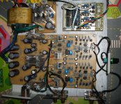
I have to report my transitor roll experience on cascode bjt on the output stage.
I tried BD139C/BD140C, KSE340/KSE350, KSC2690/KSA1220, 2SC3600/2SA1407.
Little different but I choose 2SC3600/2SA1407 in the end, KSC2690/KSA1220 come second place. I think 2SC3600/2SA1407 has a little clear and little dynamic than others. Just my opinion.
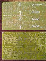
I also seperate the buffer part of the GW mkII to a single PCB layout so I can use it for other things. I really like it.
I tried BD139C/BD140C, KSE340/KSE350, KSC2690/KSA1220, 2SC3600/2SA1407.
Little different but I choose 2SC3600/2SA1407 in the end, KSC2690/KSA1220 come second place. I think 2SC3600/2SA1407 has a little clear and little dynamic than others. Just my opinion.
I also seperate the buffer part of the GW mkII to a single PCB layout so I can use it for other things. I really like it.
Last edited:
I have to report my transitor roll experience on cascode bjt on the output stage.
I tried BD139C/BD140C, KSE340/KSE350, KSC2690/KSA1220, 2SC3600/2SA1407.
Little different but I choose 2SC3600/2SA1407 in the end, KSC2690/KSA1220 come second place. I think 2SC3600/2SA1407 has a little clear and little dynamic than others. Just my opinion.
I also seperate the buffer part of the GW mkII to a single PCB layout so I can use it for other things. I really like it.
Thank you for your contribution.
Damir
Hi Damir
Just finished payment and sent you a pm with correct shipping address.
Please confirm good reception.
Just finished payment and sent you a pm with correct shipping address.
Please confirm good reception.
Hi Damir
Just finished payment and sent you a pm with correct shipping address.
Please confirm good reception.
Confirmed.
Hello
reading BOM I did found bellow differences in refer to the last ( I hope ) schematic
Wouldn't be also better , if the RC filtration would be placed after the 10k pot instead of before ??
If someone will use long cables to connect the pot to the PCB, they will act as antena and could pick up some high Hz noise which will enter the input BJT pair
Attachments
Hello
reading BOM I did found bellow differences in refer to the last ( I hope ) schematic
Wouldn't be also better , if the RC filtration would be placed after the 10k pot instead of before ??
If someone will use long cables to connect the pot to the PCB, they will act as antena and could pick up some high Hz noise which will enter the input BJT pair
You can change that about the pot as you wish.
I will check everything again next week (before you get the board) and make one post with explanation and the link in first post.
I am still waiting next payments, the rest was shipped, look PayPal For the tracking numbers.
bkdog 2 boards
scalpel 2 boards
bkdog 2 boards
scalpel 2 boards
I have not received a PayPal invoice...
I sent you just now email to the same address, check it and load to your PayPal account and check.
Damir
- Status
- Not open for further replies.
- Home
- Amplifiers
- Solid State
- No NFB line amp (GainWire mk2)