Hi,
Here is some more observations:
I changed power supply to Salas shunt and that brought some sound improvement: better details and greatly improved sound stage and smother top end. It seems my previous PSU was not the best choice for GW. I still have one more regulator to try.
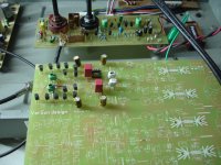
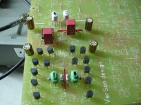
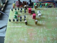
I was intrigued with my results with valve buffer and I decided to try j-fet one. I have built a small version of DCB1 and I can now confirm my previous observations: improved dynamics and fantastic bass. Anyone else tried a buffer at the input of GW?
Finally, many thanks for showing the improved version of the schematic. I will try this mod as well. At this point I have a question: is there an easy way to measure the bias current for BD139/140?
Frd
PS. Sorry for late reply - I do not have free time lately 🙂
This power supply is really overkill, just build the original GainWire shunt power supply, it's for sure not inferior to Salas one.
To measure the ops bias current, measure whole current and then detract the current for IPS (R42 or R43 voltage drop/R42) and the LF411 current(take a look in the datasheet). The current trough Q15, Q16 is less then 1 mA.
Overkill or not - point is it required no investment at all 😀
I have one more PSU to try with GW. Luckily it is smaller.
I have one more PSU to try with GW. Luckily it is smaller.
Overkill or not - point is it required no investment at all 😀
I have one more PSU to try with GW. Luckily it is smaller.
I tried my last PSU with GW and I am very satisfied with the results. In this specific circuit the PSU brought small but noticeable improvement over Salas shunt: the precision and clarity. I like the sound very much - a pleasure to listen to. GW is now a very strong performer. I still have to try the latest mods.
I tried my last PSU with GW and I am very satisfied with the results. In this specific circuit the PSU brought small but noticeable improvement over Salas shunt: the precision and clarity. I like the sound very much - a pleasure to listen to. GW is now a very strong performer. I still have to try the latest mods.
What was your last PSU? Did you ever try mine PSU?
What was your last PSU? Did you ever try mine PSU?
I did not build your PSU dadod, sorry. It would take me some of time and some more money to invest in parts. In general, I wanted evaluate GW with minimal investment, so my whole build is done "el cheapo". My total cost would oscillate around 30EUR mark and this is because I had most of the parts required.
That is also why used PSUs that I already had and that I knew.
The last PSU I used is a circuit very similar to Jung super regulator. Unfortunately, I can not share the details as this is non-public design of my friend. I am also little bit surprised myself that it outperformed Salas shunt. I must take a closer look at this and try both of them in different circuits.
I is quite possible that I will build your regulator and try it out, although I do not think this is going to happen this year. I suppose modifying the my current PCB for GW would take priority - I need to switch to two layers and make the board little bit smaller. The GW truly deserves the highest quality board and components.
Indeed the shunts can really make a difference.
IMO there is more room for improvement in this area.
Basically, the GW shunts are quite similar to the Salas V1 with a different ccs and some special "securing" circuits added.
I already absorbed a slight elegant touch from the GW shunts, that I included in my latest revisions.
Dadod did a really high quality design and I did learn a lot out of it.
Indeed the shunts can really make a difference.
IMO there is more room for improvement in this area.
Basically, the GW shunts are quite similar to the Salas V1 with a different ccs and some special "securing" circuits added.
I already absorbed a slight elegant touch from the GW shunts, that I included in my latest revisions.
Dadod did a really high quality design and I did learn a lot out of it.
Thank you for your nice word, you are to kind.
Yes.
You are very welcome, Esperado. I am curious, do you know from your long audio experience any other pre/headphone amp with possibility to change from GNFB to NGNFB just by moving one jumper?
No. I don't think it existed. That is the reason why I was really impressed by your idea. (and the way you had-it ;-)You are very welcome, Esperado. I am curious, do you know from your long audio experience any other pre/headphone amp with possibility to change from GNFB to NGNFB just by moving one jumper?
You know I'm very interested to explore if exists a 'signature' of any topology. The pro and cons. I did the same with two amps, with the same parts, one in CFA, one in VFA, as close as possible (same open loop gain, Same VAS, Same OPS). Your pre-amp is an other way to explore GNFB VS No GNFB.
More than this, as your pre-amp can be used both on linear charges (pre-amp) and speakers like(headphones) it is interesting to explore isolation /VS motional feedback.
Last, your schematic is pretty original. As I'm a little bored by the eternal reproductions of the same topologies, it was a breath of fresh air to look at it.
Last edited:
I'm confused a little.
Are bom list and schematic on post#336 the last one(final version)?
Schematic and bom not match.
where i can find the silkscreen for pcb rev.1.1 to check resistors already installed?
It is impossible to see numbers under resistors
Are bom list and schematic on post#336 the last one(final version)?
Schematic and bom not match.
where i can find the silkscreen for pcb rev.1.1 to check resistors already installed?
It is impossible to see numbers under resistors
Last edited:
I'm confused a little.
Are bom list and schematic on post#336 the last one(final version)?
Schematic and bom not match.
It was long time ago, just ask what confuses you.
What value for R17?It was long time ago, just ask what confuses you.
R36?
R22?
Where i can find the final bom?
I have install many resistors and i worry for wrong values
Last edited:
What value for R17?
R36?
R22?
Where i can find the final bom?
I have install many resistors and i worry for wrong values
OK, I can see that I need to make some order. I will edit the first post with different versions and corresponding BOM. As the same error are on the PCB I will not change resistors numbers in the schematics but will explain in BOM.
For you question, not to wait:
R17 = 2k7 (1k5 for 3.5x gain) close to jumper J2
there is other R17 with value of 6R8 in Q1 emitter
there is one more resistor defining the gain
R19 = 100R (330R for 3.5x gain) close to jumper J1
R36 = 12k, BOM is OK for it
R22 = 15k, BOM is wrong
don't hesitate to ask if more confusion provoked with my sloppy work.
ok thanks,are those c5,c6 22uf critical?
Can i use 47uf?
j1,j2 ?
Is tl071 ok for servo(just for the test period)?
Can i use 47uf?
j1,j2 ?
Is tl071 ok for servo(just for the test period)?
Last edited:
ok thanks,are those c5,c6 22uf critical?
Can i use 47uf?
j1,j2 ?
Is tl071 ok for servo(just for the test period)?
Those caps are not critical, TL071 should be OK.
J1 and J2 is the position for the jumper(only in one position at a time. CFA or NGNFB).
- Status
- Not open for further replies.
- Home
- Amplifiers
- Solid State
- No NFB line amp (GainWire mk2)


