Very nice, I am waiting your listening impression.
I've been listening Gainwire mk2 for a while now and it is time to share some
thoughts about it.
I've been using it as a headphone amplifier to drive my AKG K701 and GWmk2
does not disappoint in this setup. This is a big advantage for me.
The sound is very good, very balanced and very musical. In terms of difference
between CFA and NGNFB: both modes are very similar in sound. CFA puts emphasis
on the high frequencies, while non-negative-feedback mode puts emphasis on
midrange and bass (which is excellent).
Yesterday I made one experiment and passed a signal to GWmk2 via a buffer. That
made the sound even better. The definition and dynamics of the sound
improved a lot.
I like the sound of GWmk2, but I would not call the amp a reference one.
It shows great potential but requires some tiny bit if refinement. Mostly to
make the background "darker" if you know what I mean.
Also, I still need to test different PSUs that I have to find out which one is the
best for this circuit.
Off course there is no amp without any negative feedback.
Then change the title of this thread.
I've been listening Gainwire mk2 for a while now and it is time to share some
thoughts about it.
I've been using it as a headphone amplifier to drive my AKG K701 and GWmk2
does not disappoint in this setup. This is a big advantage for me.
The sound is very good, very balanced and very musical. In terms of difference
between CFA and NGNFB: both modes are very similar in sound. CFA puts emphasis
on the high frequencies, while non-negative-feedback mode puts emphasis on
midrange and bass (which is excellent).
Yesterday I made one experiment and passed a signal to GWmk2 via a buffer. That
made the sound even better. The definition and dynamics of the sound
improved a lot.
I like the sound of GWmk2, but I would not call the amp a reference one.
It shows great potential but requires some tiny bit if refinement. Mostly to
make the background "darker" if you know what I mean.
Also, I still need to test different PSUs that I have to find out which one is the
best for this circuit.
I don't think that differen PSU will bring improvement. The one I designed(I am not sure if you use unchenged version as you made your own PCB) is a shunt type with very low output impedance.
First improvement I will look in good stepped volume pot as the one from ELMA.
There olso possibility for improvement in using better resistor as a Dale type.
Maybe better electrolytic caps, but the FC from Panasonic are quite good.
[...] Yesterday I made one experiment and passed a signal to GWmk2 via a buffer. That
made the sound even better. The definition and dynamics of the sound
improved a lot. [...]
Could you say more about this buffer ?
Dadod, many thanks for the advices. I am not using your PSU. I decided not to build it as I have four different ones in my drawer (I have a shunt too). My original plan always assumed to try them with GWmk2 if the first listening impressions are promising. This is what I am going to do. The volume pot is next in line. I have Khozmo stepped attenuator to try as well, but I need to take it out from another device first 🙂
In terms of buffer, I used very simple ecc82 cathode follower. The canonical design. 10nF as input cap, 2.2uF at the output, CRC PSU for anode and AC for the heater. Why this one? No particular reason - it was just the first one I found in my drawer. Now I am thinking about trying DCB1 🙂
Maybe I am repeating myself, but in general the sound of GWmk2 is very good and shows promises for better. That is why I will be spending more time with this design. Having said that, I'd like to thank Dadod for sharing his work. I really appreciate that.
Dadod, many thanks for the advices. I am not using your PSU. I decided not to build it as I have four different ones in my drawer (I have a shunt too). My original plan always assumed to try them with GWmk2 if the first listening impressions are promising. This is what I am going to do. The volume pot is next in line. I have Khozmo stepped attenuator to try as well, but I need to take it out from another device first 🙂
In terms of buffer, I used very simple ecc82 cathode follower. The canonical design. 10nF as input cap, 2.2uF at the output, CRC PSU for anode and AC for the heater. Why this one? No particular reason - it was just the first one I found in my drawer. Now I am thinking about trying DCB1 🙂
Maybe I am repeating myself, but in general the sound of GWmk2 is very good and shows promises for better. That is why I will be spending more time with this design. Having said that, I'd like to thank Dadod for sharing his work. I really appreciate that.
I am waiting your further evaluation.
Hi Dadod, is there any update to the design? My preamp in CFA mode sound so good so I consider making another one.
Hi Dadod, is there any update to the design? My preamp in CFA mode sound so good so I consider making another one.
Not yet, I was thinking to design one with SMT dual transistors, but the time is flying by so fast.
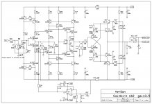
This version is better suited to drive low impedance headphones as 32 ohm Grado.
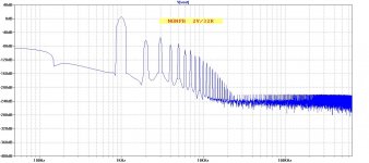
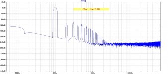
The bias for OPS is doubled from 30 mA to 60 mA and now BD139/140 transistors need a small heatsinks. The compensation is a bit changed, R39 from 22R to 47R and C2 from 220pF to 150pF. The phone output resistor decreased to 2R2 for better damping factor.
Attached FFT for 32 ohm load, distortion is much lower for 300 ohm or higher impedance phones.
Damir
Attachments
I must build this one also..... do you plan to make some pcb's ?
If there is going to be enough interested, yes.
dadod, I just discovered your thread about "Only distortion feedback". I Tried this decades ago. Well, It seems you gave-it up (as I did).
But, for what i had read, the reason was not explicitly given.
OPAs are not fast enough to return the error signal at HF (20KHz) with low enough phase error to maintain the feedback ratio of the loop as well as a constant common mode rejection (signal). So, it is too tricky. Agree ?
This is fragile, and could be used only at low frequencies in order to get impressive distortion numbers.
Last edited:
dadod, I just discovered your thread about "Only distortion feedback". I Tried this decades ago. Well, It seems you gave-it up (as I did).
But, for what i had read, the reason was not explicitly given.
OPAs are not fast enough to return the error signal at HF (20KHz) with low enough phase error to maintain the feedback ratio of the loop as well as a constant common mode rejection (signal). So, it is too tricky. Agree ?
This is fragile, and could be used only at low frequencies in order to get impressive distortion numbers.
Esperado, I never came close to the real build, just simulation and intellectual challenge. Even in the simulation it was tricky to get lowest distortion, so I came to conclusion for real life amp it will ask for expensive distortion measuring equipment and careful adjustment, so I quit. And I did not try different OPA.
This version is better suited to drive low impedance headphones as 32 ohm Grado.
The bias for OPS is doubled from 30 mA to 60 mA and now BD139/140 transistors need a small heatsinks. The compensation is a bit changed, R39 from 22R to 47R and C2 from 220pF to 150pF. The phone output resistor decreased to 2R2 for better damping factor.
Attached FFT for 32 ohm load, distortion is much lower for 300 ohm or higher impedance phones.
Damir
Is phone out and line out swap in your schematic?
What is C1= 1nF for?
I also saw R7, R8 reduce from 150 to 100 and C3, C8 from 220p -> 22p, R11 from 470 to 10 whichs you didn't mention? I just want to make sure.
With new bias = 60mA, can BC550C and BC560C in ouput buffer withstand the heat?
Is phone out and line out swap in your schematic?
What is C1= 1nF for?
I also saw R7, R8 reduce from 150 to 100 and C3, C8 from 220p -> 22p, R11 from 470 to 10 whichs you didn't mention? I just want to make sure.
With new bias = 60mA, can BC550C and BC560C in ouput buffer withstand the heat?
Good observation, phone and lineout are swapped, my mistake.
C1 is there to lower the long line cable capacitance influence and together with other compensation changes (R39, C2, R27, C3, R28, C8, R11) gives better stability for increased bias current.
New bias current heats mostly BD139/140 cascode transistors, not much the BC transistors.
Can we expect improvements also if used as a line preamp ?
I think that the line preamp is as good as it can be, don't think that those changes will improve it.
Just carefull adjustement (an an oscilloscope) . Nulling the signal as much as possible in the OPA output at 100Hz (to get rid of phase problems). But it can change quite a lot with the sligtest variation of gain in the amp and the OPA itsef, due to temp variation etc...so I came to conclusion for real life amp it will ask for expensive distortion measuring equipment and careful adjustment
You saved your time in quiting ;-)
I am waiting your further evaluation.
Hi,
Here is some more observations:
I changed power supply to Salas shunt and that brought some sound improvement: better details and greatly improved sound stage and smother top end. It seems my previous PSU was not the best choice for GW. I still have one more regulator to try.
I was intrigued with my results with valve buffer and I decided to try j-fet one. I have built a small version of DCB1 and I can now confirm my previous observations: improved dynamics and fantastic bass. Anyone else tried a buffer at the input of GW?
Finally, many thanks for showing the improved version of the schematic. I will try this mod as well. At this point I have a question: is there an easy way to measure the bias current for BD139/140?
Frd
PS. Sorry for late reply - I do not have free time lately 🙂
Attachments

- Status
- Not open for further replies.
- Home
- Amplifiers
- Solid State
- No NFB line amp (GainWire mk2)