40 years of making OTLs that defy your claims?
But the idea that a tube behaves like a tube when its in a circuit should not be a matter of debate.
But the idea that a tube behaves like a tube when its in a circuit should not be a matter of debate.
In our prticular case with Tims's OTL, if 32 ohms speakers (modified Quads 63) are in use, shall I rise the bias? How shall I find the best working point (class A)for the 6c33c ?This statement is false. We've built OTLs that had fully regulated power supplies. You can see one online at the 2016 Axpona show, called the Nirvana.
We've also used regulation in only certain portions of the circuit.
It can make a difference if the cap gets reverse biased, as in the case of an electrolytic (which is what one would need in order to not restrict low frequency bandwidth). Some might try installing a non-polar electrolytic, but they can be reverse biased too. So the solution is to use two caps in series, and then bias their junction in the middle.
This statement is false. I know of at least one OTL that was commercially available (KSS) that was direct-coupled from input to output.
This statement is also false. Class of operation has to do with the load impedance, B+ voltage and the bias point. Set the bias point and the load impedance high enough, while keeping the B+ voltage in check and the power tubes will not go into cutoff.
The tubes follow the same rules that all other tubes do- there isn't anything about their being in an OTL that prevents them from that.
Now if the load impedance is too low then it might be difficult to put enough current through the output section to achieve class A, but into a 16 ohm load its really not that challenging.
All amps distort when overloaded. OTLs can be built so that the draw on the AC line is pretty much constant, although I prefer to bias in class A2 as a lot more power is available depending on the power tube.
In the case of the 6C33, its grid current characteristics are surprisingly similar to that of a pentode power tube, so class A2 is impractical.
Regards
Reforming.
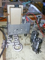
I got some 2,200 µF, 250 Volt electrolytics from IT-Tronics in Germany for $5 each. They are 9 years old but fit nicely into the existing space inside the chassis. I'm making sure they are completely reformed before fitting them. I have a tube tester unit which I built a couple of months ago for my Svetlana NOS 6J32Ps which supplies 200 Volts. I'm feeding each cap through a 220 K resistor for about 24 hours. That should do the job.Last night I heard two sharp cracking sounds from my speakers which were being fed from my OTL. The music I was playing sounded normal enough but I decided to measure the DC offset; it had shot up to 350mV on both channels. I de-powered immediately and opened the cover.
Because the problem was on both channels, I suspected a power supply issue. Lo and behold, one of the main smoothing capacitors had burst, but luckily in a sort of gentle way. It's a 3400uF 250V Panasonic hi-grade item.
I remember dropping one of them accidentally from about 1.5 Metres onto a hard floor during assembly, so I think I may have damaged it internally then. Panasonic have now taken this particular capacitor off the market, so maybe there is something else to consider, but finding an alternative which fits into the existing space may be difficult.
Attachments
I decieded to go further. As one of Tim's advices was, if possible, the balanced input, I'de like to use my Nagra PLL preamplifier which allready has balanced output.
What changes do you suggest at the first stage of the OTL (getting rid of the input caps...etc) ? How shall I manage the mfb connection (+/-)?
Apreciate anny ideea.....
What changes do you suggest at the first stage of the OTL (getting rid of the input caps...etc) ? How shall I manage the mfb connection (+/-)?
Apreciate anny ideea.....
In our prticular case with Tims's OTL, if 32 ohms speakers (modified Quads 63) are in use, shall I rise the bias? How shall I find the best working point (class A)for the 6c33c ?
Regards
That depends- what is your plate voltage under load?
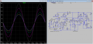
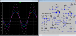
As B+/- is 150V, for 50W into 32ohms, I would expect to see a peak current of 1.77A compared to 2.5A for 25W into 8ohms. The rms voltage for 50W/32ohms is 40V at 1khz sinwave. Usualy I bias the two 6c33c at 200 mA on 8 ohms load.That depends- what is your plate voltage under load?
How many power tubes are you running?As B+/- is 150V, for 50W into 32ohms, I would expect to see a peak current of 1.77A compared to 2.5A for 25W into 8ohms. The rms voltage for 50W/32ohms is 40V at 1khz sinwave. Usualy I bias the two 6c33c at 200 mA on 8 ohms load.
How many power tubes are you running?
Attachments

That might be a bit of a trick with that tube. It tends to run really hot and has a tendency to eat its socket, so its often biased low as the reduced heat allows the socket to last a little longer.
However the 32 ohm load is going to help quite a lot with the heat, as more of the output power will be absorbed by the load rather than the output section.
However the 32 ohm load is going to help quite a lot with the heat, as more of the output power will be absorbed by the load rather than the output section.
I decieded to go further. As one of Tim's advices was, if possible, the balanced input, I'de like to use my Nagra PLL preamplifier which allready has balanced output.
What changes do you suggest at the first stage of the OTL (getting rid of the input caps...etc) ? How shall I manage the mfb connection (+/-)?
Apreciate anny ideea.....
Have you try this? If you're nervous, you can just remove the volume control, and put it in the balance input of pre-amp instead. But I can't see why it should fail in actual circuit however, do you?
Attachments
balanced input is a real possibility with this amp,
but from recent past experience where the amp is totally hum free and well behaved,
may not be really needed as far as i am concerned....
but from recent past experience where the amp is totally hum free and well behaved,
may not be really needed as far as i am concerned....
There already is one that's pretty close:i am designing an outboard output transformer to reflect 32 ohms to 4 or 8 ohms.....
www.zeroimpedance.com
yes. i followed that thread too....
i design and build all trafos used in my amps.....
Best ideea, but try 64 to get the best clas A point. Have a look to Patrik Turner point o view..... OTL-amps-pros-cons )i am designing an outboard output transformer to reflect 32 ohms to 4 or 8 ohms.....
My concern was gettin rid of the two input caps which put some phase issues and tonal modifications as well as the cost.Have you try this? If you're nervous, you can just remove the volume control, and put it in the balance input of pre-amp instead. But I can't see why it should fail in actual circuit however, do you?
You are right, but my concern is the imput caps.......if I can get rid of them.balanced input is a real possibility with this amp,
but from recent past experience where the amp is totally hum free and well behaved,
may not be really needed as far as i am concerned....
My concern was gettin rid of the two input caps which put some phase issues and tonal modifications as well as the cost.
Yes replace them with solid wire there is no phase loss but you wary of external dc on the input. Balance line has 600 ohms termination resistors, which is different to 47k of RCA input so it's good if your interconnect is very long. Nevertheless it can be done.
Attachments
You are right, but vr1 is useless as I have volume control in the line stage. and in anny case the vr1 cant work asimetrical in simetrical input, has to be cut off.Yes replace them with solid wire there is no phase loss but you wary of external dc on the input. Balance line has 600 ohms termination resistors, which is different to 47k of RCA input so it's good if your interconnect is very long. Nevertheless it can be done.
You dont think in+ and In- must be inverted , I meen I would disconnect C1 from the gain-control slider and connect it to the negative (inverting) input of the XLR socket. Then disconnect C2 and connect to the positive (non-inverting) input of the XLR socket.Yes replace them with solid wire there is no phase loss but you wary of external dc on the input. Balance line has 600 ohms termination resistors, which is different to 47k of RCA input so it's good if your interconnect is very long. Nevertheless it can be done.
Also loading the imput with 600 ohms resistors, shall change imput level as well as nfb ratio I suppose....
- Home
- Amplifiers
- Tubes / Valves
- New Tim Mellows OTL project