You dont think in+ and In- must be inverted , I meen I would disconnect C1 from the gain-control slider and connect it to the negative (inverting) input of the XLR socket. Then disconnect C2 and connect to the positive (non-inverting) input of the XLR socket.
Also loading the imput with 600 ohms resistors, shall change imput level as well as nfb ratio I suppose....
Yes, IN+ and IN- refer to opposite AC phase, not DC, but some DAC output DC as well if they're current type. NFB is still same, it's determined by 34k resistor and 1Meg ratio. There might be sight DC offset with extra ground path of both 34k resistor, not much I hope.
I just spoke with Tim. He sas :" I would keep them (C1&C2) because they produce 100% feedback at DC, which is important to minimise the offset voltage across the load. By all means include the load resistors if the manual for the Nagra(my line preamplifier PL-L) says it is capable of driving such a load"Yes, IN+ and IN- refer to opposite AC phase, not DC, but some DAC output DC as well if they're current type. NFB is still same, it's determined by 34k resistor and 1Meg ratio. There might be sight DC offset with extra ground path of both 34k resistor, not much I hope.
Also I wonder if I have to adjust the 200mA bias in case of 32 ohms load as well as the nfb resistor (1M) relativ to the 40Vrms/32ohmd output in stad of 14Vrms/8ohms.
I just spoke with Tim. He sas :" I would keep them (C1&C2) because they produce 100% feedback at DC, which is important to minimise the offset voltage across the load. By all means include the load resistors if the manual for the Nagra(my line preamplifier PL-L) says it is capable of driving such a load"
Also I wonder if I have to adjust the 200mA bias in case of 32 ohms load as well as the nfb resistor (1M) relativ to the 40Vrms/32ohmd output in stad of 14Vrms/8ohms.
If increase bias, you reduce grid swing and therefore clip earlier, in 8 or 32 ohm load the grid swing is same proportion around -50V, so -47 to -60 will change the bias current from 300mA to 100mA.
NFB controls the damping factor, and damping factor is same between 8 or 32 ohms load, but I would think damping at 8 ohms is poorer as it drawns much more current than 32 ohms load, so maybe more bias current at 8 ohms and reduce bias current at 32 ohms.
Right, theoreticaly, I shall check in practice, but I think reducing the bias at 32 ohms load (my esl63 ) shall reduce also clas A treshold , I think...If increase bias, you reduce grid swing and therefore clip earlier, in 8 or 32 ohm load the grid swing is same proportion around -50V, so -47 to -60 will change the bias current from 300mA to 100mA.
NFB controls the damping factor, and damping factor is same between 8 or 32 ohms load, but I would think damping at 8 ohms is poorer as it drawns much more current than 32 ohms load, so maybe more bias current at 8 ohms and reduce bias current at 32 ohms.
Best ideea, but try 64 to get the best clas A point. Have a look to Patrik Turner point o view..... OTL-amps-pros-cons )
That article is nonsense. It makes a lot of false assumptions and then bases the math on that (what is known as a Strawman argument).
Clearly OTLs can be practical amplifiers as they have been around since WW2. I rather doubt we would have been able to stay in business over 40 years if the amps were impractical.
My assumption is the author has never actually worked with an OTL.
So carry on, folks!
Yes, right, When I first red that, I was incited to go on not to stop. But there are also pros if you have a closer look. One was for me the ideea of using OT in an OTL design, which feets perfect with my project (OTL/ESL63)yes, read that article too, but it did not stop me building one...
This conversation has got me thinking about a project which I experimented with 25 years ago.Yes, right, When I first red that, I was incited to go on not to stop. But there are also pros if you have a closer look. One was for me the ideea of using OT in an OTL design, which feets perfect with my project (OTL/ESL63)
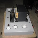
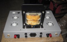
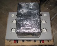
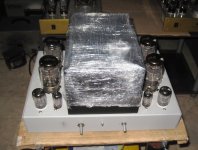
The idea was to build a triode push pull design using a spare 1 KVA Variac mains transformer which I had come across in the garage. I removed the outer housing and used the variable rotating contact as the centre tap. It was very easy to wind on the secondary from ordinary heavy plastic-insulated wire. I did not go as far as to do any measurements on the setup but with a small amount of anode current and using a pair of 811 triode transmitter modulators, the results seemed quite acceptable. It wonder would it be worth another attempt or indeed would it have any potential for the purpose of this present discussion. The really useful aspect of the big toroid was the ability to very easily play around with the output winding which required relatively few turns, as the primary has so few also. It was just an experiment at the time. I thought I might put the idea out there.
Last edited:
i would use 200 volt capacitors when i can find them....
imo, series connecting filter caps is not the best practice...
the maximum series connections i will do is two,
that is why in my build i used two 10000ufd/100 volt caps in series....
i have found 3inch 15000ufd/200volt caps but i am not sure
i want to use them either....
my thoughts too, but start building it and get the excitement of your life....😉
imo, series connecting filter caps is not the best practice...
the maximum series connections i will do is two,
that is why in my build i used two 10000ufd/100 volt caps in series....
i have found 3inch 15000ufd/200volt caps but i am not sure
i want to use them either....
I already have the tubes, sockets and applicable power transformers and it's not a terribly complicated amp...so it still has my interest.
my thoughts too, but start building it and get the excitement of your life....😉
Nobody has reported speaker destruction when fed from this amp - YET.
OK, it's living dangerously but the sound from the amp is A1. If you accidentally knock one of the 6C33Cs out of its base, you get full HT across your speaker. It's a bit more difficult to build than you think; sourcing the right components was my biggest difficulty.
It would be be completely unsuitable for a guitar amp; it's really only for pure HI-Fi aficionados The sense of reward and achievement after building it is immense when you hear the end results. BTW, there is a previous thread on the same amp which is also very informative. Reading all posts on both threads is worth the effort - both inspiring and slightly daunting.
i used output coupling cap, so when one output tube died due to cathode grid short, only the + fuse blew...
 moved all posts about guitar amps to its own thread here: http://www.diyaudio.com/forums/instruments-amps/303444-otl-amps-guitar-duty.html
please stick to the original intent of this thread, OTL for hifi...
please stick to the original intent of this thread, OTL for hifi...
Good thinking AJT. I've had my fill of guitar amps, having built two of them. Now let's get back to business.
Is 6BN11 ok with the voltages?
I saw the maximum anode voltage for 6BN11 was lower than for EF86 but don't remember the actual voltages on the EF86 in the Mellows design. Maybe you are doing something different but I assumed something similar.
I saw the maximum anode voltage for 6BN11 was lower than for EF86 but don't remember the actual voltages on the EF86 in the Mellows design. Maybe you are doing something different but I assumed something similar.
i was counting on the maximun ratings, the tube will rin plate dissipation of 500mW and 200mW each so they should run cool....
Cool.
I know you're not a newbie. I just wanted to think that out loud.
I'm an 'armchair' builder...hoard parts, change my goals, delay start, delay completion, rinse, repeat...
I know you're not a newbie. I just wanted to think that out loud.
I'm an 'armchair' builder...hoard parts, change my goals, delay start, delay completion, rinse, repeat...
- Home
- Amplifiers
- Tubes / Valves
- New Tim Mellows OTL project