looking good.....can you simulate using 47 volt 1 watt zeners as i described?
also there ought to be a cap at the g2 supply of the ef86...
in the 12ax7 input stage, i would like to put 10ufd bypass caps...
can you also simulate for a 6201/12at7 inputs?
also there ought to be a cap at the g2 supply of the ef86...
in the 12ax7 input stage, i would like to put 10ufd bypass caps...
can you also simulate for a 6201/12at7 inputs?
looking good.....can you simulate using 47 volt 1 watt zeners as i described?
also there ought to be a cap at the g2 supply of the ef86...
in the 12ax7 input stage, i would like to put 10ufd bypass caps...
can you also simulate for a 6201/12at7 inputs?
1) I am aware of the method you mentioned, like this one is a little involved, but I"ll give it a try.
2) Yes, about 10u on g2.
3) Can do, very soon.
Last edited:
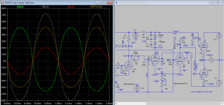
Here is your 1st request. I think it's working very well, no noticeable changes now. Sonic wise as audio now passed through solid state devices, please comment later as you implemented it. Next is 12at7 as front-end.
Attachments
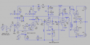

thanks, the diodes are shunted by 0.22ufd/400vdc cap so that at ac, it bypasses the diodes.....
this is meant to address reliability issues when using the ef86....
this may raised some eyebrows, but if you want reliability, i think this is the way to do it...
for the ef86 drivers, the output swing positive halves are important, they should be of the same amplitude, an equal 50 volt peak would be nice....
to address this symmetry issue, i think the thing to do is to add a pot
between the two 100k plate resistors, a 50k trimpot can be trialed,
with the midspan wiper connected to B+....
My oppinion is that Tim's project is perfect as it is. Nevertheless, I tried several improvement, but only feu were succesfull. FET CCS instad of R7 was one of them as well as separating the power supplyes (eg. +/-150V; +146V; -460V; )
the thing with Tim's topology is its almost dc coupling that i really like....
and listening to it confirmed it as having great potential....
thanks, the diodes are shunted by 0.22ufd/400vdc cap so that at ac, it bypasses the diodes.....
this is meant to address reliability issues when using the ef86....
this may raised some eyebrows, but if you want reliability, i think this is the way to do it...
for the ef86 drivers, the output swing positive halves are important, they should be of the same amplitude, an equal 50 volt peak would be nice....
to address this symmetry issue, i think the thing to do is to add a pot
between the two 100k plate resistors, a 50k trimpot can be trialed,
with the midspan wiper connected to B+....
Right, that should make it sounds better. As you bring down the plate to closer level to the other one, this LTP stage now is getter better in 2nd harmonic cancellation, odd harmonic is unchanged, so there is a difference if you drop 50V or 100V (one or two zener), so you would implement jumps to select 1) no zener 2) one zener 3) two zeners.
Last edited:
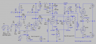
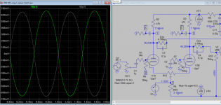
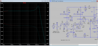
Here are 12AT7 sim plots, also included FFTs of zener and no zener plot of original 12ax7.
Attachments
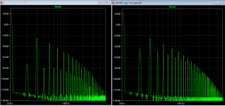
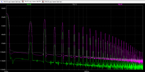
i plan to use just one cap to shunt the zeners, and i use 2ufd input caps because i have a lot of them....
i am not sure how to interpret the results, perhaps some more knowledgeable members
can chime in.....but i read somewhere that 3rd harmonics helps the bass...
i am not sure how to interpret the results, perhaps some more knowledgeable members
can chime in.....but i read somewhere that 3rd harmonics helps the bass...
QED....I was using Mullard NOS, but one failed and the fuse blow on negativ rail.
Sometimes NOS tubes have such isues. That's why I decieded to burn and runn the valves several weeks and the check again and match.
The amp is up and running again 😀😀😀
No tube problem but... and isolation problem of one of the LM317(6,3vdc supply)regulators 😱
Through A broken mica isolator the -430v touched ground

my 6c33 OTL used all ac filament heating and is very very quiet,
no hum, no buzz, even if you pit your ears close the the speakers....
i also used dc filament supplies, but never used any regulators,
just a CRC filter, my reasoning, less parts that can fail.....
but this is just me.....😀
no hum, no buzz, even if you pit your ears close the the speakers....
i also used dc filament supplies, but never used any regulators,
just a CRC filter, my reasoning, less parts that can fail.....
but this is just me.....😀
RIGHT, mine is quiet too with ac filament. I recomand less complications .....my 6c33 OTL used all ac filament heating and is very very quiet,
no hum, no buzz, even if you pit your ears close the the speakers....
i also used dc filament supplies, but never used any regulators,
just a CRC filter, my reasoning, less parts that can fail.....
but this is just me.....😀

I have orderd a filament transformer for AC heating 😉RIGHT, mine is quiet too with ac filament. I recomand less complications .....

I also used AC filament supplies; absolutely no hum whatsoever.I have orderd a filament transformer for AC heating 😉
Rectifiers have the potential to add noise, which means an additional issue to deal with. So I normally prefer to use elevated AC heaters instead. YMMV
Sent from my LG-D801 using Tapatalk
Sent from my LG-D801 using Tapatalk
Hi,
And how does that solve the noise problem ?
As much as I love OTLs, I own one and designed many, you must realize that the B+/B- caps are in the signal path.
Best is to build mono blocks and either use a very good xformer or at least separate heater xformers from HT rail xformers. Overrate them generously.
Do not use regulators unless you're willing to regulate all stages which is close to impossible with an OTL.
Having a cap at the output to block DC has no sonic influence I'm aware of. Think it through.
There's little point in eschewing caps to block DC between stages, you end up using a cap to block it anyhow.
Moreover, all OTLs I know of are cap coupled, see above.
All OTL are inevitably class AB in operation. When hammered they tend to distort and/or pop HT rail fuses.
That said, yes they can sound incredibly real.
Cheers, 😉
This statement is false. We've built OTLs that had fully regulated power supplies. You can see one online at the 2016 Axpona show, called the Nirvana.Hi,
Do not use regulators unless you're willing to regulate all stages which is close to impossible with an OTL.
We've also used regulation in only certain portions of the circuit.
It can make a difference if the cap gets reverse biased, as in the case of an electrolytic (which is what one would need in order to not restrict low frequency bandwidth). Some might try installing a non-polar electrolytic, but they can be reverse biased too. So the solution is to use two caps in series, and then bias their junction in the middle.Having a cap at the output to block DC has no sonic influence I'm aware of. Think it through.
This statement is false. I know of at least one OTL that was commercially available (KSS) that was direct-coupled from input to output.There's little point in eschewing caps to block DC between stages, you end up using a cap to block it anyhow.
Moreover, all OTLs I know of are cap coupled, see above.
This statement is also false. Class of operation has to do with the load impedance, B+ voltage and the bias point. Set the bias point and the load impedance high enough, while keeping the B+ voltage in check and the power tubes will not go into cutoff.All OTL are inevitably class AB in operation. When hammered they tend to distort and/or pop HT rail fuses.
The tubes follow the same rules that all other tubes do- there isn't anything about their being in an OTL that prevents them from that.
Now if the load impedance is too low then it might be difficult to put enough current through the output section to achieve class A, but into a 16 ohm load its really not that challenging.
All amps distort when overloaded. OTLs can be built so that the draw on the AC line is pretty much constant, although I prefer to bias in class A2 as a lot more power is available depending on the power tube.
In the case of the 6C33, its grid current characteristics are surprisingly similar to that of a pentode power tube, so class A2 is impractical.
Last edited:
- Home
- Amplifiers
- Tubes / Valves
- New Tim Mellows OTL project