

Set picture 😱
Very nice build indeed. Giving access to to the 4 trim-pots on the exterior of the chassis is well worth the extra work; it makes life much easier. There will be a considerable amount of adjustment to be done for the initial 100 hours or so. I run mine at 175 mA and the O/P offset strays no further than 5 mV from day to day (after 15 minutes of warm-up, of course).
I like the design of the tube sockets; they are different than what you usually see on these amps. Well done and I bet it sings sweetly. It's the best tube power amp design I have ever built. Happy listening.
![IMG_0109[493] diy.jpg](/community/data/attachments/551/551340-231e1ca583d13eb5796aa8e1089783e8.jpg?hash=Ix4cpYPRPr)
Do you know a supplier for that kind of socket?...they look nice.I bought them in 2014 for 18 euro a piece 😀😀
First Failure
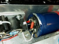
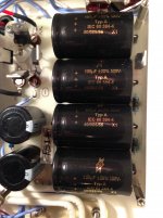
Last night I heard two sharp cracking sounds from my speakers which were being fed from my OTL. The music I was playing sounded normal enough but I decided to measure the DC offset; it had shot up to 350mV on both channels. I de-powered immediately and opened the cover.
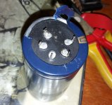
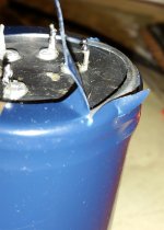
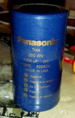
Because the problem was on both channels, I suspected a power supply issue. Lo and behold, one of the main smoothing capacitors had burst, but luckily in a sort of gentle way. It's a 3400uF 250V Panasonic hi-grade item.
I remember dropping one of them accidentally from about 1.5 Metres onto a hard floor during assembly, so I think I may have damaged it internally then. Panasonic have now taken this particular capacitor off the market, so maybe there is something else to consider, but finding an alternative which fits into the existing space may be difficult.
Last night I heard two sharp cracking sounds from my speakers which were being fed from my OTL. The music I was playing sounded normal enough but I decided to measure the DC offset; it had shot up to 350mV on both channels. I de-powered immediately and opened the cover.
Because the problem was on both channels, I suspected a power supply issue. Lo and behold, one of the main smoothing capacitors had burst, but luckily in a sort of gentle way. It's a 3400uF 250V Panasonic hi-grade item.
I remember dropping one of them accidentally from about 1.5 Metres onto a hard floor during assembly, so I think I may have damaged it internally then. Panasonic have now taken this particular capacitor off the market, so maybe there is something else to consider, but finding an alternative which fits into the existing space may be difficult.
Attachments
Good catch!
On my Krell 150 clone Snyder monos years ago, I got the same indications on PS caps going bad and was able to shut down just in the nick of time!
Regards
David
On my Krell 150 clone Snyder monos years ago, I got the same indications on PS caps going bad and was able to shut down just in the nick of time!
Regards
David
i am building two new OTL's this year, one is 6C33 based,
the other using the 6336 tubes, topology will use the Tim Mellows design...
the other using the 6336 tubes, topology will use the Tim Mellows design...
i am building two new OTL's this year, one is 6C33 based,
the other using the 6336 tubes, topology will use the Tim Mellows design...
There's no doubt that getting rid of that output transformer is a great idea. The OTL gives a whole now dimension to the sound of audio. I'm a big fan now.
There's no doubt that getting rid of that output transformer is a great idea. The OTL gives a whole now dimension to the sound of audio. I'm a big fan now.
indeed, i wanted to do the 6336 as a pp, but then it got me thinking,
without the OPT's building it OTL is another good option....
i am an OTL convert, i confess.....😎
After A listening sesion of 5 hours it ended with a bang and smoke 🙁🙁
The 1K R31 and 32 resistors are burnt out 😕 what went wrong ?
The 1K R31 and 32 resistors are burnt out 😕 what went wrong ?
Picture😉
Well, I'd suspect C16 at first, but it could be something else. I'm sure you will get more replies with other suggestions.After A listening sesion of 5 hours it ended with a bang and smoke 🙁🙁
The 1K R31 and 32 resistors are burnt out 😕 what went wrong ?
Those resistors should have only low current through them, and should not get burnt. I agree with the capacitor theory. Was it wired in with the correct polarity? (positive terminal to ground).The 1K R31 and 32 resistors are burnt out 😕 what went wrong ?
The problem is that when those resistors fail you lose the negative bias supply and the return path for the current through the EF86 stage. Their anodes will pull up and will take the grids on the output tubes more positive. That will causes a large increase in current through the output tubes. Result = Bang.
Well, I'd suspect C16 at first, but it could be something else. I'm sure you will get more replies with other suggestions.
Indeed, C16 would seem to be the prime suspect. If your bias potentiometer RV3 is attached to the chassis (or otherwise grounded), it could conceivably be a problem with insulation breakdown causing it to short circuit to ground, which would also cause R31 and R32 to burn out. Otherwise C16 seems about the only possible candidate. It does have a high voltage on it, so it needs to be properly rated for the job.
Of course C16, along with C17, are wired "unusually" in the sense that their positive terminals, not their negatives, are connected to ground. But I would assume you must have that right, otherwise the amplifier probably wouldn't have lasted for 5 seconds, let alone 5 hours.
Chris
Of course C16, along with C17, are wired "unusually" in the sense that their positive terminals, not their negatives, are connected to ground. But I would assume you must have that right, otherwise the amplifier probably wouldn't have lasted for 5 seconds, let alone 5 hours.
When current limited (by the resistors in this case), reversed electrolytics can sometimes start to re-form in reverse. Then it's anyone's guess when they will fail. Although, I think if that had been the case, the bias voltage would probably have been obviously incorrect.
@brommermartin - do you have a photo showing the components in question?
Judged from the degree of burnt, it's not gradual heat up (noted the PCB does not change colour or sign of heat) but maybe abrupt due to increase of current drawn (> 30mA) in a short time. Are the resistor 1/2W, are they opened? Capacitors usually leak gradually maybe not so abrupt, but tubes can, so maybe one of the EF86 is shorted.
Last edited:
- Home
- Amplifiers
- Tubes / Valves
- New Tim Mellows OTL project