Great, for consistency I've attached the updated schematic and KiCAD archive (the Gerbers don't change). I gather you have got used to soldering SOIC-8 packages?
I have gotten better! I changed out my solder tip to a curved one and it was a game changer for me. I am curious, would it be possible to have the high-pass filter elements on a switch too (like the gain adjustment)? That would allow me to use the preamp on other projects as well (for general bioacoustic monitoring). Your thoughts?
What cut-off frequency would you want for the general bioacoustic monitoring mode? < 16 Hz or some value in the human hearing range, but smaller than 1 kHz? Are there any requirements on start-up time?
Hey Marcel, would a 80Hz setting be too high? I don't know what the start-up time means, but I suspect it wouldn't matter for what we are doing with the preamps. Thanks!
You know better than I do whether 80 Hz is too high, as you know more about bioacoustic monitoring.
Start-up time is the time between the moment you apply the 5 V supply and the time the amplifier starts working as it is supposed to. It is presently about 1 second. How long could it be without becoming inconvenient?
Start-up time is the time between the moment you apply the 5 V supply and the time the amplifier starts working as it is supposed to. It is presently about 1 second. How long could it be without becoming inconvenient?
Hey Marcel, I think anywhere between 80-160Hz would not interfere with any of the signals we would get for our research. Start-up time wouldn’t matter as I can adjust the recorder start time to adjust. Thanks again!
Hey Marcel, I think anywhere between 80-160Hz would not interfere with any of the signals we would get for our research. Start-up time wouldn’t matter as I can adjust the recorder start time to adjust. Thanks again!
One more question, is C13 necessary since the LME49721 is single supply topology? Thanks!
 Keep your forum clean and clutter free. Please do NOT quote the entire post just above yours. This is mentioned in the rules section.
Over-quotes have been removed.
As you want to connect the output to a sound card's microphone input with phantom supply, there could be a higher DC voltage across R5 than at the output of the second op-amp. That's why I included C13.
Considering Pano's remark, could you reply without quoting when the message you reply to is just above your reply?
My apologies, I didn't really understand what that was in regard to. I will incorporate going forward. Thanks!
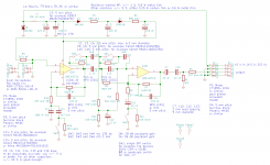
I haven't tried to fit it on the PCB design yet, but the version with switchable cut-off frequency would be something like this. The lower cut-off setting is about 130 Hz. The modified amplifier needs about 5 seconds to settle instead of about 1 second.
Attachments
Last edited:
Awesome! I wasn't sure it would be possible/feasible to put the HPF on a switch. This will greatly improve the usefulness of the preamp to beyond just night flight calls of birds. I am already formulating a frog call project that would be able to utilize the preamp.
On another note, PCBWay screwed up my last order of 20 boards so I have a pretty good credit with them now. I will hold off on ordering until we can get a layout for the new design. The thought has also crossed my mind that you may want a copy of your designed PCB. If you would like I can certainly send you a copy or two (PM me your address). Thanks Marcel!
On another note, PCBWay screwed up my last order of 20 boards so I have a pretty good credit with them now. I will hold off on ordering until we can get a layout for the new design. The thought has also crossed my mind that you may want a copy of your designed PCB. If you would like I can certainly send you a copy or two (PM me your address). Thanks Marcel!
What name do you want to give the frog-compatible version? I can put the name in the front legend and/or in top metal.
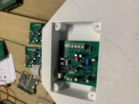
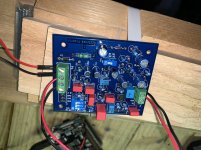
What about calling it the "ecotone" or "ecotones" preamp? One more thing that came up I wanted to ask about. The current PCB footprint fits near perfectly in the microphone housing as previously designed. There is room for expansion horizontally. There is about 1.2 cm of room in that direction. I have attached a photo to illustrate. Would it be possible to add the new switches and stay within those dimensions? If not, no big deal. Thanks!
Attachments
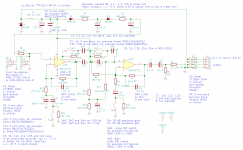
See the attachments. Switches SW2...SW4 together are one triple DIP switch; each of them has a single switch footprint in the KiCAD database, but as I placed those at a 0.1 inch pitch on the board, you can actually not use three single switches but only one triple switch. Everything (only just) fits in the area you asked for.
Attachments
Last edited:
This looks great! I will try to order the parts tonight. PCBway is being annoying again and not reviewing the gerber for some reason. Hopefully they will get to it sometime tonight. Thanks Marcel!!!
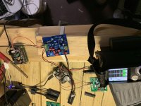
Hey! Yes indeed. I meant to make a post last week but got too busy. I built it a couple weeks ago and been testing since then. I attached a couple photos of the setup. Switches 2,3, and 4 work well. One thing I noticed and wanted to ask about is if there is levels of filtering depending on which switch is used. It seemed like with just switch 2 pushed it was filtering some. Would love to know your thoughts.
Attachments
- Home
- General Interest
- Everything Else
- Need Advice for a Weird Project