There are two ifs: if the bird sang equally loud on both recordings and if there are never any low-frequency sounds driving your sound card into clipping when it is set to maximum gain, then your conclusions are totally correct.
As a sanity check and to determine whether you could further reduce the noise floor with a homemade preamplifier, you could run the experiment of post #17, assuming your set-up doesn't prevent recording the microphone input when there is no microphone connected. I could do step C for you if you like.
As a sanity check and to determine whether you could further reduce the noise floor with a homemade preamplifier, you could run the experiment of post #17, assuming your set-up doesn't prevent recording the microphone input when there is no microphone connected. I could do step C for you if you like.
There are two ifs: if the bird sang equally loud on both recordings and if there are never any low-frequency sounds driving your sound card into clipping when it is set to maximum gain, then your conclusions are totally correct.
As a sanity check and to determine whether you could further reduce the noise floor with a homemade preamplifier, you could run the experiment of post #17, assuming your set-up doesn't prevent recording the microphone input when there is no microphone connected. I could do step C for you if you like.
Sorry, got busy for a couple of days. I will try to get this done today. Thank you for your help!
I am curious if I could implement this AGC amplifier in front of the sound blaster (Electret Microphone Amplifier - MAX9814 with Auto Gain Control ID: 1713 - $7.95 : Adafruit Industries, Unique & fun DIY electronics and kits). This would help me a lot with the some situation regarding finding a gain setting that works for most situations. I used this is the past with a recorder that had the function built into it for night flight calls and it worked quite well. Would there be a way to implement a high pass filter into it?
I'm sure there is, but the question is again whether you need it. Automatic gain control is also something you can do digitally afterwards if you want to, as long as there is a fixed gain setting that is high enough to amplify the microphone's noise well above the sound card noise, yet low enough to prevent clipping. So with no preamplifier and the sound card set to +30 dB, do you run into clipping in some practical situations?
By the way, the electret microphone capsule on that Adafruit module has 14 dB more equivalent acoustical noise than the POM-2730L-HD-R you linked to in the opening post, 34 dB(A) SPL versus 20 dB(A) SPL, so I would definitely not use the Adafruit microphone. In fact the Adafruit number is quite normal for small electret microphones, while the POM-2730L-HD-R's noise level is unusually good, similar to small-diaphragm professional microphones.
By the way, the electret microphone capsule on that Adafruit module has 14 dB more equivalent acoustical noise than the POM-2730L-HD-R you linked to in the opening post, 34 dB(A) SPL versus 20 dB(A) SPL, so I would definitely not use the Adafruit microphone. In fact the Adafruit number is quite normal for small electret microphones, while the POM-2730L-HD-R's noise level is unusually good, similar to small-diaphragm professional microphones.
I'm sure there is, but the question is again whether you need it. Automatic gain control is also something you can do digitally afterwards if you want to, as long as there is a fixed gain setting that is high enough to amplify the microphone's noise well above the sound card noise, yet low enough to prevent clipping. So with no preamplifier and the sound card set to +30 dB, do you run into clipping in some practical situations?
By the way, the electret microphone capsule on that Adafruit module has 14 dB more equivalent acoustical noise than the POM-2730L-HD-R you linked to in the opening post, 34 dB(A) SPL versus 20 dB(A) SPL, so I would definitely not use the Adafruit microphone. In fact the Adafruit number is quite normal for small electret microphones, while the POM-2730L-HD-R's noise level is unusually good, similar to small-diaphragm professional microphones.
Hey Marcel. Here is the link for the tests from post 17. Let me know what you think. Thanks again for your help!
WeTransfer
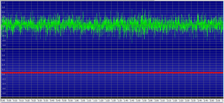
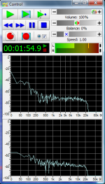
When you look at the waveforms, it seems like the microphone dominates by a huge margin, but this is actually almost completely due to the microphone's noise below 300 Hz (condenser microphones always have a large noise increase at low audio frequencies). When you look at higher frequencies, the microphone still dominates, but not by a large margin.
In the frequency range of interest, so above 1 kHz, the noise would drop by about 2.32 dB if you could somehow completely eliminate the noise of the sound card. Of course any practical microphone preamplifier has some noise of its own, so you will never reach that 2.32 dB, but maybe 2 dB?
To give you an impression of how much (or how little) 2.32 dB is, I WeTransferred an edited bird recording where the noise level is increased by 2.32 dB from 40 seconds onwards (I didn't know a way to decrease it). Link: WeTransfer
Attachments
Just wanted to circle back to this. I was able to the use the MAX9814 Electret Microphone Amplifier (Electret Microphone Amplifier - MAX9814 with Auto Gain Control ID: 1713 - $7.95 : Adafruit Industries, Unique & fun DIY electronics and kits) and swapped out the mic element with the POM-2730L-HD-R (http://www.puiaudio.com/pdf/POM-2730L-HD-R.pdf) with what appears to be great success. I still need advice on a few things.
Is there a way to add some high-pass filter to the setup? I would rather stay away from digital filtering if possible as it increases time in my workflow and I suspect the software I use to detect the flight calls has a harder time picking up the sounds. The other question I have is where to place the amplifier. Is it ok to place it at the end of the cable run (~25 feet) close to the sound card or should it be up near the mic? It would be easier to place it near the sound card as that is where the power source is located and I wouldn't need to run more wiring. Thanks in advance!
Is there a way to add some high-pass filter to the setup? I would rather stay away from digital filtering if possible as it increases time in my workflow and I suspect the software I use to detect the flight calls has a harder time picking up the sounds. The other question I have is where to place the amplifier. Is it ok to place it at the end of the cable run (~25 feet) close to the sound card or should it be up near the mic? It would be easier to place it near the sound card as that is where the power source is located and I wouldn't need to run more wiring. Thanks in advance!
With the MAX9814, you get a noise floor that is about 1 dB higher than when you connect the microphone straight to the Sound Blaster card and set the card to maximum gain, so I guess you do this because the compression makes it easier for your flight calls detection software?
Presumably you don't want the compressor to respond to low-frequency sounds that get filtered off, so that means you need a high-pass between the microphone and the MAX9814. On the other hand, a high-pass between MAX9814 and sound card can suppress some of the low-frequency noise of the MAX9814.
The simplest solution I can come up with, is to replace C9 (cap between microphone and MAX9814) with a 2.2 nF NP0 (a.k.a. C0G) capacitor and to add a 100 nF capacitor (either NP0/C0G or some kind of film capacitor) between the output of the MAX9814 and the sound card's input. I will see if I can come up with something better than that.
I think you can place the amplifier at the end of the cable if you use a well-shielded cable and if there are no strong sources of interference around. Treble loss due to the cable capacitance will be quite small; the corner frequency will be around 34 kHz with a cheap 280 pF/m PVC-insulated cable, and well over 100 kHz when you use a low-capacitance cable, such as 75 ohm coax (RG-59 for example).
If you should place the MAX9814 board at the beginning of the cable, you will need to put a resistor between the MAX9814 and the cable because according to its datasheet, the MAX9814 can't directly drive large capacitive loads. 100 ohm is probably enough.
This would be a better solution if you can get it onto the PCB, but that will require quite a bit of three-dimensional soldering.
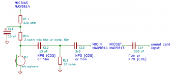
Splitting the 2.2 kohm microphone bias resistor into 220 ohm + 2 kohm with a capacitor at the junction (R13, R14, C11) is an optional change to reduce the noise slightly, it has nothing to do with the high-pass filtering. The microphone supply of the MAX9814 is rather noisy, C11 now filters off that noise.
C12, R15, C13 and C14 are the actual high-pass filter components.
Attachments
Marcel, you are awesome! Thank you so much for that diagram. I ordered the parts and will check back in when I get something made.
Got the parts in late last week. I may have gotten the capacitor for C11 as it doesn’t appear to have a +/- side to it. It’s also fairly large. In the schematic is MICBIAS the same as vdd on the amplifier? Thanks!
MICBIAS was meant to be pin 13 of the MAX9814, but using VDD (pin 5, or pin 2 of the connector) may also work if your supply is clean enough.
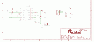
Attached is the schematic of the Adafruit module (from Downloads | Adafruit AGC Electret Microphone Amplifier - MAX9814 | Adafruit Learning System ), the idea was to remove R3, C9 and the original microphone and connect my circuit to the corresponding pins of the MAX9814. If it is more convenient, you can also leave C9 in and connect my C13 to Adafruit's C9 (series connection of C13 and C9), you then only need to remove R3 and the microphone. In either case, you need to find a way to mount the extra components.
Removing two-pin SMDs is easy when you have two soldering irons, one for each side. If the SMDs are small enough, you can also heat up both sides with only one iron and shift them from their pads.
Can you post a picture of the capacitor you got for C11? (You can attach it to your post using the Go Advanced button and the Manage Attachments form.) A film capacitor will work fine as C11 in my circuit, it is just a lot larger and more expensive than the aluminum electrolytic capacitor I had in mind.
Attachments
Last edited:
MICBIAS was meant to be pin 13 of the MAX9814, but using VDD (pin 5, or pin 2 of the connector) may also work if your supply is clean enough.
Attached is the schematic of the Adafruit module (from Downloads | Adafruit AGC Electret Microphone Amplifier - MAX9814 | Adafruit Learning System ), the idea was to remove R3, C9 and the original microphone and connect my circuit to the corresponding pins of the MAX9814. If it is more convenient, you can also leave C9 in and connect my C13 to Adafruit's C9 (series connection of C13 and C9), you then only need to remove R3 and the microphone. In either case, you need to find a way to mount the extra components.
Removing two-pin SMDs is easy when you have two soldering irons, one for each side. If the SMDs are small enough, you can also heat up both sides with only one iron and shift them from their pads.
Can you post a picture of the capacitor you got for C11? (You can attach it to your post using the Go Advanced button and the Manage Attachments form.) A film capacitor will work fine as C11 in my circuit, it is just a lot larger and more expensive than the aluminum electrolytic capacitor I had in mind.
Hey Marcel, well that went disastrously wrong. I don't have the skill or equipment to pull these changes off. I think if I am to scale this up I will need to get a preamp design and then send off to a PCB manufacturer. My main needs would be a high gain (40-50dB), high-pass filter (~800-1000 MHz), work with the electret mic elements, through hole components, and run off the raspberry pi 5 volt power supply. If you have any recommendations on design or suggestions I would be most grateful.
Last edited:
That's a pity!
The cheapest alternative that requires least soldering would be some software solution that high-pass filters and adjusts volume without requiring your intervention. My knowledge of Raspberry Pi programming is insufficient to give you any advice on how to do that, but maybe there is someone reading this thread who knows more about it.
Regarding the hardware approach: earlier in the thread you were OK with 12 V supply voltage and relatively large SMD components. Under those conditions, the circuit of post #18 could be sufficient, especially when L1 is replaced with a through-hole alternative, such as a 100 uH axial through-hole inductor. The circuit has a gain of only 28 dB when you use only the positive output, but with your sound card set to +30 dB, the total is still 58 dB, similar to what you have with the OldBird preamplifier and 0 dB sound card gain.
The filter is only first order and the dual op-amp is only available in SMD packages. The largest package it comes in is SO8, with 1.27 mm (0.05 inch) pitch.
By changing the circuitry around the second op-amp, I could change the filtering order from first to third and increase the gain if needed. There would be no negative output anymore, but you don't use it anyway.
I made a new thread to see if anyone knows a software solution, see Inserting software high-pass and gain between sound card and application software
That's a pity!
The cheapest alternative that requires least soldering would be some software solution that high-pass filters and adjusts volume without requiring your intervention. My knowledge of Raspberry Pi programming is insufficient to give you any advice on how to do that, but maybe there is someone reading this thread who knows more about it.
Regarding the hardware approach: earlier in the thread you were OK with 12 V supply voltage and relatively large SMD components. Under those conditions, the circuit of post #18 could be sufficient, especially when L1 is replaced with a through-hole alternative, such as a 100 uH axial through-hole inductor. The circuit has a gain of only 28 dB when you use only the positive output, but with your sound card set to +30 dB, the total is still 58 dB, similar to what you have with the OldBird preamplifier and 0 dB sound card gain.
The filter is only first order and the dual op-amp is only available in SMD packages. The largest package it comes in is SO8, with 1.27 mm (0.05 inch) pitch.
By changing the circuitry around the second op-amp, I could change the filtering order from first to third and increase the gain if needed. There would be no negative output anymore, but you don't use it anyway.
Hey Marcel, I could add a voltage booster to the rpi power output to get it to 12 volts. I will see if I can get someone to make a Gerber file and get some PCBs made up. I learned today that pcbway can also populate the boards. Might give that a shot. Thanks Marcel!
Please wait, I can modify the circuit to run off a 5 V supply. It will take a few extra resistors and capacitors, but will cost you less than an extra boost converter.
The thing I don't understand: according to post #1, "My setup runs off a 12V solar powered battery that powers the raspberry pi. The raspberry pi sends out 5V to a 9V step up converter that then powers the preamp." Why can't the preamplifier run off the 12 V solar powered battery?
The thing I don't understand: according to post #1, "My setup runs off a 12V solar powered battery that powers the raspberry pi. The raspberry pi sends out 5V to a 9V step up converter that then powers the preamp." Why can't the preamplifier run off the 12 V solar powered battery?
Please wait, I can modify the circuit to run off a 5 V supply. It will take a few extra resistors and capacitors, but will cost you less than an extra boost converter.
The thing I don't understand: according to post #1, "My setup runs off a 12V solar powered battery that powers the raspberry pi. The raspberry pi sends out 5V to a 9V step up converter that then powers the preamp." Why can't the preamplifier run off the 12 V solar powered battery?
Hey Marcel, I wasn’t thinking correctly. The system does run off a 12 volt battery but the power is managed by the raspberry pi. If I wired the preamp directly to the battery it would stay on the whole time. If I power it through the raspberry pi the preamp would turn on and off with the raspberry pi and save power. I apologize for not thinking of that earlier. Thanks again for your help!
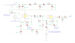
How about this? Runs off the 5 V, has only one component that you can't get in a through-hole package (the dual op-amp in an SO-8 package), the gain is switchable between 28 dB and 57 dB and it includes a fixed third-order Butterworth high-pass filter at 1 kHz. If you don't need the 57 dB position, R7 can be replaced with a short and C9, C10, R9 and SW1 can be removed. The output is not balanced anymore.
Attachments
Last edited:
How about this? Runs off the 5 V, has only one component that you can't get in a through-hole package (the dual op-amp in an SO-8 package), the gain is switchable between 28 dB and 57 dB and it includes a fixed third-order Butterworth high-pass filter at 1 kHz. If you don't need the 57 dB position, R7 can be replaced with a short and C9, C10, R9 and SW1 can be removed. The output is not balanced anymore.
Oh Marcel, I could kiss you! Thank you so much for this. I will work on trying to get some PCBs made and make some for testing. I will check back in soon.

- Home
- General Interest
- Everything Else
- Need Advice for a Weird Project