I hope you haven't ordered the parts yet, because I woke up this morning and realized I had made a mistake. I have to add one resistor and recalculate some component values.
I hope you haven't ordered the parts yet, because I woke up this morning and realized I had made a mistake. I have to add one resistor and recalculate some component values.
No worries. I am still trying to find someone that can do the PCB layout for me. Thanks for double checking!
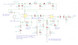
Here is the corrected circuit. The main change is in the way the second op-amp's bias voltage is made (circuitry around R12 and R13).
I made some additional changes as well:
A. R14 added to prevent thumps when switching the gain, R8 slightly reduced to compensate for R14's effect on the gain in low-gain mode, R7 also reduced to keep it equal to R8
B. C13 added to improve reliability when the phantom supply of the sound card's microphone input exceeds the bias voltage at the output of the second op-amp
C. Impedance of the network C5-C6-R6-R11 scaled up to make the filter response in low-gain mode a bit more accurate (smaller error term due to the current flowing from R6 to R7).
If you are not in a hurry, I can also design a PCB for it.
Attachments
Here is the corrected circuit. The main change is in the way the second op-amp's bias voltage is made (circuitry around R12 and R13).
I made some additional changes as well:
A. R14 added to prevent thumps when switching the gain, R8 slightly reduced to compensate for R14's effect on the gain in low-gain mode, R7 also reduced to keep it equal to R8
B. C13 added to improve reliability when the phantom supply of the sound card's microphone input exceeds the bias voltage at the output of the second op-amp
C. Impedance of the network C5-C6-R6-R11 scaled up to make the filter response in low-gain mode a bit more accurate (smaller error term due to the current flowing from R6 to R7).
If you are not in a hurry, I can also design a PCB for it.
This looks great! I am totally ok with you designing the PCB as you are the one most familiar with the circuit. I am curious how the input and output connections would work and be mounted. Again, you rock!
You would need headers, connectors and/or terminal blocks for the microphone, the audio output and the supply. It's probably a good idea to at least keep the microphone connection well separated from the rest. Do you have a preference for a header/connector/terminal block type?
You would need headers, connectors and/or terminal blocks for the microphone, the audio output and the supply. It's probably a good idea to at least keep the microphone connection well separated from the rest. Do you have a preference for a header/connector/terminal block type?
Sounds good. No preference for connector type. The mic elements are subject to the environment and will likely die fairly often, so a quick and easy connection that I can replace would be preferable.
I assume you will put the microphone capsule on one end of the long cable and the amplifier on the other end, provided this doesn't cause any interference problems. Is that correct?
I assume you will put the microphone capsule on one end of the long cable and the amplifier on the other end, provided this doesn't cause any interference problems. Is that correct?
Whatever is best. I 3d print the mic housing so I can design it however to hold the amplifier or put it in box at the base before it goes into the sound card.
See the attachments, which are a zip file with Gerbers and a zip file with what I hope to be a complete KiCAD database. I write "hope to be", because I have several projects in one directory, which made KiCAD include lots of irrelevant stuff that I had to remove myself. I hope I didn't remove too much. For your information, KiCAD is an open source PCB layout program.
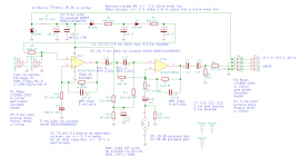
Anyway, for the connectors I included two footprints, one for a 0.1 inch pitch (shrouded) header and one for a 5 mm pitch terminal block, so you can mount the one you prefer. The advantage of the headers is that you can buy them in gold-plated versions that don't oxidize and therefore keep giving good contact, even for low-level signals, but you may need a special crimping tool to connect cables to them. The terminal blocks only require a screwdriver, but as they are meant for power applications, they are never gold plated.
Anyway, for the connectors I included two footprints, one for a 0.1 inch pitch (shrouded) header and one for a 5 mm pitch terminal block, so you can mount the one you prefer. The advantage of the headers is that you can buy them in gold-plated versions that don't oxidize and therefore keep giving good contact, even for low-level signals, but you may need a special crimping tool to connect cables to them. The terminal blocks only require a screwdriver, but as they are meant for power applications, they are never gold plated.
Attachments
Last edited:
By the way, if you supply the amplifier from a USB port, C1 needs to be much reduced in value, because USB ports can only handle a limited capacitive load. L1 may then also need to be changed to another value.
By the way, if you supply the amplifier from a USB port, C1 needs to be much reduced in value, because USB ports can only handle a limited capacitive load. L1 may then also need to be changed to another value.
Hey Marcel, this looks fantastic! I am very excited about this. The power output comes from the 5v header pins on the raspberry pi with maximum current being 16mA. Will that work?
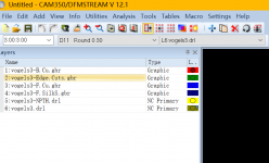
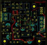
I went ahead and tried to order the PCBs from PCBway and ran into an issue. It through an error mentioning the solder mask layer was missing. I attached an image of what they sent. Thanks again for all your help! Very much looking forward to testing this board out.
Attachments
By the way, PUI Audio has an electret microphone that has an equivalent acoustical noise level that is even lower than the type you use now, 14 dB(A) instead of 20 dB(A). It also has a 6 dB higher sensitivity. It is called the AOM-5024L-HD-R. It's bigger than the POM-2730L-HD-R, 9.7 mm diameter instead of 6 mm.
By the way, PUI Audio has an electret microphone that has an equivalent acoustical noise level that is even lower than the type you use now, 14 dB(A) instead of 20 dB(A). It also has a 6 dB higher sensitivity. It is called the AOM-5024L-HD-R. It's bigger than the POM-2730L-HD-R, 9.7 mm diameter instead of 6 mm.
You're a legend Marcel! I got the PCBs and parts ordered. Very much looking forward to getting a few built.
I am curious about the electret mic you mentioned. The POM one has a frequency response weighted on higher frequencies. Wouldn't that be advantageous for bird calls? I guess I am not exactly sure what specifications I should be looking for in the case of this project.
You definitely need a low equivalent acoustical noise level. PUI Audio specifies it indirectly, as the A-weighted signal-to-noise ratio for a 94 dB sound pressure level, 1 kHz signal (94 dB SPL corresponds to 1 Pa RMS of pressure variation). All in all, 94 dB minus whatever A-weighted signal-to-noise ratio is specified gives you the A-weighted acoustical equivalent of the microphone's noise.
For example, the AOM's 80 dB corresponds to 14 dB(A) equivalent acoustical noise. That's quite good: lower than most professional stage microphones, but not quite as low as some large-diaphragm studio condenser microphones. Professional microphones are much better at handling very loud sounds, though.
The sensitivity is less important, as you can always make up for a low sensitivity by using a low-noise, high-gain microphone preamplifier. The POM and AOM actually both have a rather high sensitivity. By the way, because the difference in equivalent acoustical noise is exactly compensated for by the difference in sensitivity, the calculations of post #26 apply equally to the POM and the AOM.
Regarding the peaking of the POM, according to your opening post, the frequencies of interest are mainly between 5 kHz and 8 kHz. The POM peaks a bit higher in frequency: between 8 kHz and 16 kHz, up to about 6 dB around 12 kHz. The AOM is almost flat up to 13 kHz or 14 kHz and then gradually rolls off. In either case, 5 kHz to 8 kHz is in the flat part.
Hey Marcel, I ordered some of those mic elements to test. I have all the parts in and the pcb came in today. I am in the process of assembling and don’t know how to orient the op amp. There is a white line on the op amp but can’t make sense of the traces to figure out which direction goes where. Hope all is well.
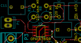
Hey Marcel, thank you for the info. I was able to get a board together, but I wasn’t able to get it to work. For p3 the positive is on top and negative on the bottom? For p4 it would be 5v voltage in positive on top and ground beneath then output positive then output ground? When assembled this way I don’t get any voltage at the input to power the mic. I will try to put another one together tomorrow morning to see if I may have cooked something. Thanks!
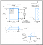
Hi Hal, you connected P4 incorrectly. If there was no other connection between power ground and output ground when you tried, you have a good chance that the circuit survived. Otherwise it could be that you either blew up the dual op-amp (which is very difficult to desolder without hot air station) or the Schottky diode D3.
The 1 mm (0.039 in) wide trace to D3 is the +5 V, so with P4 on the right, you have from top to bottom ground, output, ground, +5 V.
The 1 mm (0.039 in) wide trace to D3 is the +5 V, so with P4 on the right, you have from top to bottom ground, output, ground, +5 V.
Attachments
- Home
- General Interest
- Everything Else
- Need Advice for a Weird Project