With a bit of luck, D3 protected the dual op-amp and you either have to replace nothing, if D3 survived, or only D3, if it has turned into a big short.
Hi Hal, you connected P4 incorrectly. If there was no other connection between power ground and output ground when you tried, you have a good chance that the circuit survived. Otherwise it could be that you either blew up the dual op-amp (which is very difficult to desolder without hot air station) or the Schottky diode D3.
The 1 mm (0.039 in) wide trace to D3 is the +5 V, so with P4 on the right, you have from top to bottom ground, output, ground, +5 V.
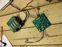
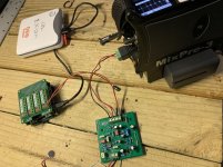
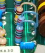
Hey Marcel, I am such a bonehead. Yep, I cooked the first one. I built another this afternoon and I am now getting a signal from the mic. It doesn't sound right though. It sounds muffled and muted. There is also a lot of interference buzzing and pops coming from the raspberry pi. I confirmed the mic is getting a little over 2v. Any ideas on what could be going on? I attached a photo of my setup. Thanks!
Attachments
Could you check a couple of things?
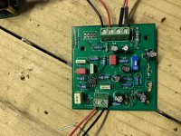
1. Are pins 5...8 of the dual op-amp soldered properly? It looks a bit funny on the photos.
2. Are C8 and C9 really 220 pF and not 220 nF? I can't see it on the photos, but they seem rather large for 220 pF NP0.
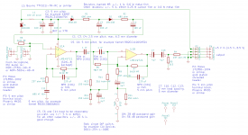
3. What DC voltages do you see at pins 1 and 7 of the OPA1678 with the microphone connected? It should be about 2 V (between 1.4 V and 2.96 V) for pin 1 and about 1.5 V for pin 7.
By the way, the resistor footprints were meant for vertical mounting, but horizontal should also work.
1. Are pins 5...8 of the dual op-amp soldered properly? It looks a bit funny on the photos.
2. Are C8 and C9 really 220 pF and not 220 nF? I can't see it on the photos, but they seem rather large for 220 pF NP0.
3. What DC voltages do you see at pins 1 and 7 of the OPA1678 with the microphone connected? It should be about 2 V (between 1.4 V and 2.96 V) for pin 1 and about 1.5 V for pin 7.
By the way, the resistor footprints were meant for vertical mounting, but horizontal should also work.
Hey Marcel, not sure about how well those pins are soldered. Anyway I could check? The voltage between pins 1 is 2.3V and I am not getting a reading on pin 7 at all. Pin 8 is reading 4.9V. Attached a pic of the caps I used for c8 and 9. Thanks again for your help!
Attachments
The capacitors are fine, they are just a bit large because they are rated for 1000 V. No problem there.
Could you switch off the supply and check the resistance between pin 5 of the dual op-amp and the upper pad of R11, between pin 6 and the lower pad of R6 and between pin 7 and the left pad of R7? (With "upper", "lower" and "left" I mean the orientation on the layout plot when P4 is on the right.) They should all be close to 0 ohm, any value above 2 ohm indicates poor soldering of that specific pin.
Could you switch off the supply and check the resistance between pin 5 of the dual op-amp and the upper pad of R11, between pin 6 and the lower pad of R6 and between pin 7 and the left pad of R7? (With "upper", "lower" and "left" I mean the orientation on the layout plot when P4 is on the right.) They should all be close to 0 ohm, any value above 2 ohm indicates poor soldering of that specific pin.
Pin 5 and r11 = 0.2; pin 6 and r6=0.2; pin 7 and r7=0.2. I will put another one together and try my best with the op amp to make sure it is seated right. Third time is a charm!
If all these connections are 0.2 ohm, apparently the soldering is OK, even though they look bad on the photos. Are you sure the pin of the meter was touching the pin of the IC and not its pad on the PCB? With the supply applied again, what DC voltages do you see at pins 5 and 6? How about the DC voltage at the side of R11 that is closest to C12?
Last edited:
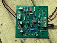
Marcel! Third time was a charm! I re-did my solder job on the op amp and it is working beautifully now. Sounds really, really good for my purposes. This preamp is far superior to the other I was using.
At the 27dB level it works similarly to the old preamp. When I flip the switch to the 57dB level it seems to clip at the slightest bit of signal. Any ideas on that? Thanks again for your help on this. I will go work on my soldering skills.
At the 27dB level it works similarly to the old preamp. When I flip the switch to the 57dB level it seems to clip at the slightest bit of signal. Any ideas on that? Thanks again for your help on this. I will go work on my soldering skills.
Great that it works now, at least in the low-gain mode!
About the high-gain mode: the most likely problems I can think of are that either the gain of the sound card is still at +30 dB, giving a total gain of 58 dB and 86 dB in the low- and high-gain modes, or that there is something wrong around R9 or C10. When R9 is shorted, the gain of the second stage in the high-gain mode goes through the roof, when C10 is shorted, the biasing of the second stage is messed up in the high-gain mode.
Have you tried the AOM-5024L-HD-R microphone and if so, how do you like it?
Interesting development. The higher gain level seems to be working better after letting it stay on for a while. I did try to AOM mic element and it seems to handle the louder signals better, lower self noise, and doesn’t seem any different to frequency response. I think I will switch to these as it will allow me to run the recorder a little higher level gain without so much clipping.
I was wondering if switching out some of the capacitors to “audio grade” versions would give any better performance? Hope all is well!
I was wondering if switching out some of the capacitors to “audio grade” versions would give any better performance? Hope all is well!
That's strange. Maybe C12's dielectric had to recover from long storage - at least that's the only thing I could think of. It could also be due to C12 having a much too large value, but on the photos it looks exactly like all the other 4.7 uF capacitors. Does the amplifier need a long time to settle every time you switch it on or only the first time? Is the DC voltage at pin 7 of the dual op-amp close to 1.5 V?
"Audio grade" usually means exceedingly expensive without any clear technical benefits, so I wouldn't try that.
"Audio grade" usually means exceedingly expensive without any clear technical benefits, so I wouldn't try that.
If the voltage at pin 7 is wrong or slowly varies all over the place, it could be a loose connection somewhere between R12/R13 and pin 5 of the op-amp. For example, when one side of R11 got disconnected, leakage currents will slowly change the bias voltage of the second op-amp.
That's strange. Maybe C12's dielectric had to recover from long storage - at least that's the only thing I could think of. It could also be due to C12 having a much too large value, but on the photos it looks exactly like all the other 4.7 uF capacitors. Does the amplifier need a long time to settle every time you switch it on or only the first time? Is the DC voltage at pin 7 of the dual op-amp close to 1.5 V?
"Audio grade" usually means exceedingly expensive without any clear technical benefits, so I wouldn't try that.
Hey Marcel, the voltage at pin 7 is exactly 1.5. Very little movement at that point. I am beginning to think it may be the recorder I am using for testing the preamp. When I switched to another recorder and manipulated some of the gain settings I was getting better performance than with the other recorder. Overall, I am really happy with this preamp...thank you! I really appreciate your help.
I am curious, could we name the preamp? Your file names for the project reminded me of something. One of my family names is Birdsong (ironic, I know) which was derived from Vogelsang. Could we name it the Vogelsong Preamp? I also like Bubo Preamp (latin/genus name for owl).
So it works as intended now? That's great!
Of course you can name it. I chose those file names vogels3.*** because vogels also means birds in Dutch (unlike the Germans we don't spell all nouns with a capital), and it was my third circuit in this thread (after the preamplifier with 12 V supply and first-order filter and the proposed Adafruit module modifications that didn't work out). By the way, bird song is vogelzang in modern Dutch, but a few centuries ago it could also be spelled with an s, like in German.
Of course you can name it. I chose those file names vogels3.*** because vogels also means birds in Dutch (unlike the Germans we don't spell all nouns with a capital), and it was my third circuit in this thread (after the preamplifier with 12 V supply and first-order filter and the proposed Adafruit module modifications that didn't work out). By the way, bird song is vogelzang in modern Dutch, but a few centuries ago it could also be spelled with an s, like in German.
Thanks Marcel! How do you make a clean radius when you bend the leads for the resistors? I am also curious if the op amp LME49721 would work in the preamp. It was recommended to me a few years back when I first started trying to figure out improving the audio aspect of night flight call research.
I don't know, I never get the bends to look that nice on anything I build myself.
The LME49721 should work very well in this preamplifier when you change R12 to 150 kohm. The DC bias voltage at pin 7 of the LME49721 should then be 2.5 V. You will have a bit more headroom than with the original circuit.
The LME49721 should work very well in this preamplifier when you change R12 to 150 kohm. The DC bias voltage at pin 7 of the LME49721 should then be 2.5 V. You will have a bit more headroom than with the original circuit.
Last edited:
Mind you, with the LME49721, the supply voltage range will be 4.5 V to 5.5 V rather than 4.5 V to 10 V. No problem when you supply it from the Raspberry Pi's 5 V directly, just make sure never to connect it to your 9 V boost converter by mistake.
Got it. Just built one with the LME49721 op amp and replaced the resistor you mentioned and it sounds pretty dang good to me. I think it may have slightly less noise, but I don't really trust my ears to tell the difference. If I am pretty quick about it I can get one built in about 25 minutes. I plan to send some out to colleagues soon for some additional testing. Thanks again!
- Home
- General Interest
- Everything Else
- Need Advice for a Weird Project