they don't show any obvious signs of being fakes. is the printing inked or laser etched? it should be laser etched
laser etching goes into the surface, ink stays on the top of the surface. take a dab of heat sink grease and rub it into the lettering. if it goes into the letters and makes them show up better, it's etched. if it doesn't, they're printed.
I wonder how often fake transistors have been blamed when the real problem was the design(er) ?
It takes a lot of money and know how to start up a fabrication unit.
Why bother if you cant sell your fakes easily ?
It takes a lot of money and know how to start up a fabrication unit.
Why bother if you cant sell your fakes easily ?
laser etching goes into the surface, ink stays on the top of the surface. take a dab of heat sink grease and rub it into the lettering. if it goes into the letters and makes them show up better, it's etched. if it doesn't, they're printed.
The Heatsink Compound enhanced the engraving so I guess these stand a reasonable chance of being genuine.
I'll try loading one of them up to 15A and see if it can hold its own.
I managed to get around to building six of the devices into my DIY-PASS Aleph 4 output stage having previously matched them.
Loading them up to 100mA each they seem OK. Next step will be to push them up to 4A.
Loading them up to 100mA each they seem OK. Next step will be to push them up to 4A.
I bought eight MJL4302A and eight MJL4281A trannies.
I measured them with a cap tester between E and C
Don't know if this is the right way and came out with the following result:
MJL4302A: 9,53
9.9
9,96
9.94
10,45
10,35
10,41
10,37
MJL4281A: 9,53
9,48
9,43
9,52
9,50
9,40
9,42
9,15
are those fake or not and what is the best way to find out please explane?
They all have the sign ON and the seller told me they are OnSemi
Last edited:
check out this thread - especially post #22:I bought eight MJL4302A and eight MJL4281A trannies.
are those fake or not and what is the best way to find out please explane?
They all have the sign ON and the seller told me they are OnSemi
http://www.diyaudio.com/forums/solid-state/154216-possible-fake-toshiba-sanken-transistors-3.html
You could try building a little test circuit and seeing how close to the SOA they will operate.
This will only detect small dies and not rebadged power transistors.
Measurement of Hfe may help identify fakes that pass the SOA test.
This will only detect small dies and not rebadged power transistors.
Measurement of Hfe may help identify fakes that pass the SOA test.
Sorry for the stupid question how do I've to build a test circuit?
What do I need?
What do I need?
Last edited:
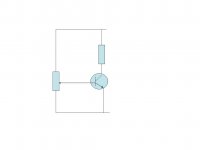
SOA Testing
First of all you need to study and understand the datasheet.
MJL4281A is rated at 350V and 15A BUT NOT SIMULTANEOUSLY
The SOA graphs show that the device can operate at 15A with a Vcc of 15V for one second. The important factor is Ptot = 230W.
So we have to pick somewhere under the SOA curve and within Ptot.
Lets use 8A and 24V, that gives us Ptot = 8x24=200W.
You will need a 24V 8A power supply. A 3 Ohm 25W resistor and a Large Heatsink.
You will need a 5W 220R potentiometer or a variable voltage source.
Basically, start with 0V on the base of the transistor and slowly increase the voltage until current starts to flow.
You should be able to increase the current within the SOA (up to 10A briefly) and the transistor should survive.
Attachments
Andy's test only works if the case (Tc) is held at 25degC.
This demands that the test signal is a short pulse (1 second) and then off until the transistor junction (Tj) is back down to 25degC.
I would do a high temperature test and de-rate the SOA for operating test Tc.
I would also choose the SOA voltage "knee" just before secondary breakdown occurs, about 50Vce.
Try 100W, i.e. 2A @ 50Vce.
Find the Tc at which the de-rating factor is 0.435 (100W/230W).
Test Tc = 150degC - [0.435 * 125Cdegrees] = 95.6degC
If Ta = 21degC the delta T = 74.65Cdegrees.
The required [Rth c-s + Rth s-a] = 74.65/100W ~ 0.75 C/W
If the device is thermally coupled (thermal compound and no insulator) to the heatsink expect Rth c-s ~ 0.2C/W This leaves Rth s-a ~ 0.55C/W
100W, 50Vce and 2A, will raise the 0.55C/W heatsink to ~ 55degrees above ambient.
The test Tc will be ~ 20degrees above the sink temperature. Test Tc will take the device to it's maximum de-rated SOA for 100W dissipation.
Last edited:
Fake 2SJ74
I bought some 2SJ74's, thinking I would be able to match them myself, as I had 2SK170's already.
Well the 2SJ74 were very strange, in build and specs:
how they looked like:

All had scratches, one also showed an old typenumber

This is how they looked from a good source:

And these were the measurements,
top the fakes
and bottom the real ones (and matching 2SK170's)
View attachment selectie 2SK170, 2SJ74.pdf
They costed the same, so this was not an el cheapo trap. Yes, I got my money back.
take care
albert
I bought some 2SJ74's, thinking I would be able to match them myself, as I had 2SK170's already.
Well the 2SJ74 were very strange, in build and specs:
how they looked like:
All had scratches, one also showed an old typenumber
This is how they looked from a good source:
And these were the measurements,
top the fakes
and bottom the real ones (and matching 2SK170's)
View attachment selectie 2SK170, 2SJ74.pdf
They costed the same, so this was not an el cheapo trap. Yes, I got my money back.
take care
albert
the second pic looks like the old number was J271, but that doesn't make any sense because a J271 is a 60A MOSFET in a TO-220 case... unless it's a Siliconix number J271
a J271 (national semiconductor, siliconix or fairchild) is a general purpose p-channel jfet with a far lower transconductance. since the process for this device has been licensed to 6 manufacturers, it's likely these fets are much cheaper and plentiful than the 2SJ74 would be.
a J271 (national semiconductor, siliconix or fairchild) is a general purpose p-channel jfet with a far lower transconductance. since the process for this device has been licensed to 6 manufacturers, it's likely these fets are much cheaper and plentiful than the 2SJ74 would be.
no, because the original numbers are clearly visible along the top of the face of the device, embedded horizontally, and the fake numbers are printed sideways vertically
My guess is the fake problem will only get WORSE. That's why you need to save ANY discarded electronics you can find!
the second pic looks like the old number was J271, but that doesn't make any sense because a J271 is a 60A MOSFET in a TO-220 case... unless it's a Siliconix number J271
a J271 (national semiconductor, siliconix or fairchild) is a general purpose p-channel jfet with a far lower transconductance. since the process for this device has been licensed to 6 manufacturers, it's likely these fets are much cheaper and plentiful than the 2SJ74 would be.
You are right. I looked at the device again today, and indeed it reads J271 (but the J is hard to read because of part of the new 'imprint' was lasered across it).
J271 is a P-Channel Switch designed for low level analog switching sample and hold circuits and chopper stabilized amplifiers, from Fairchild. Indeed, Idss between 6 and 50. Not a hifi device! Not for audio at all.
Albert
Last edited:
- Home
- Design & Build
- Parts
- My Transistors, original or copy?