Hi Capt Grogg,
2SC2240.
That pair is excellent. You should also see many 2SA872 and 2SC1775 among others. Really strong performers, and reliable. I can't comment on any KEC types beyond the fact that sometimes the lead pin outs are different.
-Chris
2SC2240.
That pair is excellent. You should also see many 2SA872 and 2SC1775 among others. Really strong performers, and reliable. I can't comment on any KEC types beyond the fact that sometimes the lead pin outs are different.
-Chris
i haven't as yet seen any KEC versions of the 2SA970, but try a search on datasheetarchive.com for a KTA970 and see what comes up. the "licensed" portion of the part number (i.e. A970, or C2240) belongs to the original manufacturer. if they license it out, the part made under license will have at least the digits and usually the polarity/speed letter (A,B.C.D). ON licensed the process for the 2SA1302 and 2SC3281 from Toshiba, and created a whole line of audio output transistors with it, and uses part numbers usually ending with 1302 and 3281 (i.e. NJL1302 and NJL3281). Fairchild licensed the process for the 2SC5305 from Sanyo and makes it with the part number KSC5305. these manufacturers meet or exceed the reliability requirements of the original maker KEC does the same thing with the parts that they sucessfully license. KEC licensed the 2SC3112 from Toshiba and makes it as the KTC3112. Toshiba is a stickler for meeting reliability criteria, and has a very comprehensive reliability program of their own. KEC must have met Toshiba's requirements with the C3112, but not the C2240.
when i see a counterfeit in my shop, i often hear "but that's a generic substitute, it should work". if a fake Toshiba says Toshiba on it, it's not a "generic replacement", it's a counterfeit. the manufacturers that buy licensing from Toshiba and Sanyo put their own logo and version of the part number on the device, NOT Toshiba's logo.
and yes, by the way KEC does make a KTA970. since they sucessfully licensed the number, i would imagine that the reliablity is up to snuff. i don't know what's wrong with their KTC3200 process, but they should try to fix it (maybe that will be released as a KTC3200A?)
Last edited:
The reason for asking the question about if anyone has encountered fakes, was that the 2240/970 usually are marked with white lettering, and I noticed that some of my stash have the brownish lasermarking. I cant post a picture, my camera stopped working😕
Toshiba has some time recently begun marking with laser etching. KEC also uses laser etching. you would have to look in Toshiba's Reliability Program documentation to see what their current marking methods are. it will be in the chapter called "Packaging". it took a bit of digging to find it a couple of years ago... i'll see if i can find it this week. as for what you are thinking might be bogus parts, measure the capacitances and beta and compare.
query about pedigree of my toshiba sc5200 transistors
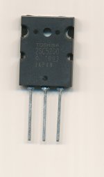
I recently bought some of these transistors from a fairly reputable (?) company called Futurlec. However because of the faint printing on the face side I have doubts about whether these are genuine Toshiba products. Can anyone tell from the picture whether or not these are genuine?
I recently bought some of these transistors from a fairly reputable (?) company called Futurlec. However because of the faint printing on the face side I have doubts about whether these are genuine Toshiba products. Can anyone tell from the picture whether or not these are genuine?
Attachments
Maybe we can measure beta and capacitances of several popular parts, contribute the data and then make it a sticky? Kinda genuine traits look up table?
I recently bought some of these transistors from a fairly reputable (?) company called Futurlec. However because of the faint printing on the face side I have doubts about whether these are genuine Toshiba products. Can anyone tell from the picture whether or not these are genuine?
REAL!
query about pedigree of my toshiba sc5200 transistors
Thank you all for replying. I haven't used them yet but will assume they are "kosher"
Thank you all for replying. I haven't used them yet but will assume they are "kosher"
it's actually very simple, check the capacitances.
Can you plse explain a simple way of measuring (output capacitance?).
I bought an MJ15003 but appeared doubtful so I bought another in a different store to use so now I have this Motorola branded MJ15003 which I'm about 50/50 if it's fake.
Marking is:
M (motorola logo)
MJ15003
MEXICO
0314
case is shiny, steel and the glass seals are blue and big similar to genuine devices.
I wasn't exactly sure when Motorola stopped producing semiconductors which made me doubt it and decided to buy from another store and used that instead.
edit: my device is similar to the geniune device description from here:
http://sound.westhost.com/fake/fake-mj.gif
taken from:
Counterfeit Transistors
Last edited:
Can you plse explain a simple way of measuring (output capacitance?).
the way it's done by the manufacturers is with 10 volts reverse bias applied to the B-C junction (isolated through a 10Meg resistor so the voltage source doesn't interfere with the measurement).the B-C (input) capacitance is then measured. the C-E capacitance is the output capacitance, and is usually measured with no DC voltages applied (but some manufacturers may apply a bias voltage. if so it will be stated in the test conditions).
ON was spun off from Motorola in 1999. a date code of 03 is bogus
thanks, that's what I thought but wasn't exactly sure at the store. I should have just used it before installing the known genuine device. So I could push it hard and see if it will blow up. 😛
you might find out as soon as you apply power. Vceo of the MJ15003 is 140V, and for a 2N3055 (the most common die used in fakes) it's only 60V.
in any case, you won't have to push it hard, since most fakes will die as soon as you try to use them with a speaker. i've seen fakes work ok with a resistive load, but as soon as they get to about half power with a speaker, the inductive kick from the speaker takes them outside their SOA and they're gone instantly.
in any case, you won't have to push it hard, since most fakes will die as soon as you try to use them with a speaker. i've seen fakes work ok with a resistive load, but as soon as they get to about half power with a speaker, the inductive kick from the speaker takes them outside their SOA and they're gone instantly.
Last edited:
The application is only 20V max (DC regulated powersupply based on LM723 - There is a SMPS with PFC delivering 20V @ 7.5A max, pass transistor drops this to whatever I adjust it to). Worst case dissipation is on a short circuit with 20V 7.5A. I originally used a 2N3772 but it was pushing it to max dissipation. A hard lesson on SOA and temperature derating.
I am interested to do this also. We have a bunch of old stock transistors.
the way it's done by the manufacturers is with 10 volts reverse bias applied to the B-C junction (isolated through a 10Meg resistor so the voltage source doesn't interfere with the measurement).the B-C (input) capacitance is then measured. the C-E capacitance is the output capacitance, and is usually measured with no DC voltages applied (but some manufacturers may apply a bias voltage. if so it will be stated in the test conditions).
An externally hosted image should be here but it was not working when we last tested it.
An externally hosted image should be here but it was not working when we last tested it.
An externally hosted image should be here but it was not working when we last tested it.
you might find out as soon as you apply power. Vceo of the MJ15003 is 140V, and for a 2N3055 (the most common die used in fakes) it's only 60V.
in any case, you won't have to push it hard, since most fakes will die as soon as you try to use them with a speaker. i've seen fakes work ok with a resistive load, but as soon as they get to about half power with a speaker, the inductive kick from the speaker takes them outside their SOA and they're gone instantly.
I'm not a school trained EE just an audiophile who builds stuff. So how does one sort out the fake transistors from the real ones? There ought to be a test bench circuit that one could use and apply real world loads to sort out the bad ones before one assembles a project. Apply the top collector to emitter voltage or exceed the collector to emitter breakdown voltage??? This ought to be a simple test circuit that allows measuring beta/hfe to allow matching and also c-b capacitance. Thanks, Ray
I am interested to do this also. We have a bunch of old stock transistors.
An externally hosted image should be here but it was not working when we last tested it.
An externally hosted image should be here but it was not working when we last tested it.
An externally hosted image should be here but it was not working when we last tested it.
assuming those are genuine for the moment, i'm drooling...
you need the data sheet, and you need to physically compare them to known originals. then if they are physically correct, the junction capacitances can be compared to known originals. for further testing, a curve tracer with the ability to nondestructively detect secondary breakdown is required (and for that many devices, the curve tracer is probably the best route to go)
- Home
- Design & Build
- Parts
- My Transistors, original or copy?