bentoronto
And now for the real test: can you record something played with and without the MFB connected? A small chance my cowbell might be revealing.
Sorry, no cowbell for practial reason
 . However attached are some instruments to listen to with Mfb and No mfb. I hope this will do and that you hear some difference...😉
Attachments
Can you look at the accel output? This would be affected by the first modal cone breakup but would also reveal resonances in other structure such as the accel mounting etc. Or maybe you have already observed this...
Yes, in post #116 I have the open sensor output at various cone amplitudes. The stepped input frequency was limited to 3kHz. Next time I remove the driver I will measure higher up in frequency.
bentoronto
Anyone who sees the plot will immediately claim they detect the 1000 Hz flaw. But anyone not seeing the plot first will never hear it or its absence.
I think you are right here. The flaw was reduced to half with the tweeter polarity reversed which contributed with another symmetrical dip at 3kHz. In total a more flat FR and cleaner step response it seems to be.🙂
...The flaw was reduced to half with the tweeter polarity reversed which contributed with another symmetrical dip at 3kHz. In total a more flat FR and cleaner step response it seems to be.🙂
Not quite clear what happened, but sounds like artefacts of mic location (interacting with crossover behaviour) is what you are picking up. Everywhere in the room there will be phase interaction in FR tests.
Exactly what you get when you run an FR with L and R playing simultaneously... except in this case the interaction is across the whole compass but more visible in the FR curves in the upper treble.
To understand the crossover region audible behaviour, good to simply run woofers and tweeters separately and add them by eye.
B.
FR is measured at 1m distance from acoustic center with one speaker only using mls and sine gated. Both show the same result in regards to dips. Also the baffel dispersion contribution with a 5dB increase just before the dip making it worse. I think the XO is a 12dB HP/LP. Could this be an issue with the phase?
FR is measured at 1m distance from acoustic center with one speaker only using mls and sine gated. Both show the same result in regards to dips. Also the baffel dispersion contribution with a 5dB increase just before the dip making it worse. I think the XO is a 12dB HP/LP. Could this be an issue with the phase?
Depending on the mic location, there can be interactions caused only by the electric phases, only by distances to the mic, or both. But excepting concentric drivers, there can't be a location with no interaction, excepting some special azimuth that Linkwitz could compute.
I'm just guessing here, but try comparing two mic locations separated by maybe 10 cm (3.937 inches*) to change relative distances to the two drivers to see what might be related to mic location interaction.
B.
* the idiotic conversion is an old Canadian joke
Sorry, no cowbell for practial reason
Very good test pieces.
After a bit of looping back and forth for comparison, clearly audible that the MFB is working well. For both selections, the first few seconds (just when louder notes appear in both cases) should convince anybody.
Like all such recordings, your room is adding a bit of reverb mud. But the benefit of the MFB is coming through.
Ditto the eternal problem of such tests of how to match loudness levels when the FR isn't quite the same.
Anybody who can't hear the difference might want to visit a friend with better speakers (esp electrostatic).
For sure, folks can say, "the non-MFB sound is OK with me". But these pieces demonstrate what can be achieved with MFB if you value that impact.
B.
Depending on the mic location, there can be interactions caused only by the electric phases, only by distances to the mic, or both.
B.
* the idiotic conversion is an old Canadian joke
There is a 90+ degree electrical difference in the XO design. Together with irregularities in the phase of the drivers it seems to favor the reversed polarity. Moving the mic 3.986" * confirm this.
* regarding the joke I was told once that in US they get closer to the metrics inch by inch😀
Very good test pieces.
After a bit of looping back and forth for comparison, clearly audible that the MFB is working well. For both selections, the first few seconds (just when louder notes appear in both cases) should convince anybody.
Like all such recordings, your room is adding a bit of reverb mud. But the benefit of the MFB is coming through.
B.
Thanks for your comments bentoronto.
The set up of both speakers was not in favor of the recording. As you mention the room contributed a lot with early reflections and booming. Despite this, there is a clarity high up in frequencies of both instruments and also in voices.
I still hear well above 15kHz at 67 years of age and that is partly because I listened to low volume music and drive car longdistance wearing earplugs 😛. I recommend checking the hearing if MFB is not considered as a step forward.
That said and now convinced by this experience, I will put interest in MFB and build something challenging. Hopefully with support from some of you "top notch experts" in this forum that impresses me so much. Where to start, that is the question?
...That said and now convinced by this experience, I will put interest in MFB and build something challenging. Hopefully with support from some of you "top notch experts" in this forum that impresses me so much. Where to start, that is the question?
This is what I tried next... 🙂
MFB for ACI SV12 Drivers using Piratelogic Electronics
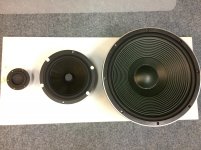
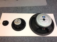
My first MFB project might be with focus of one of the three speakers as in the photo. A 15# Coral bass with underhung voice coil, a 8" Eton with stiff carbon fibre cone and long throw voce coil and finally two TangBand 3# with longthrow voicecoil connected i series.
Targets
1) Reduced volume
2) Reduced distortion
3) Low -3dB Fs
Most interesting I find the two 3" bass in series with only one sensor in a smallest cabinet. Is that at all thinkable? And anyone, is this thread the place to start the project?
Targets
1) Reduced volume
2) Reduced distortion
3) Low -3dB Fs
Most interesting I find the two 3" bass in series with only one sensor in a smallest cabinet. Is that at all thinkable? And anyone, is this thread the place to start the project?
Attachments
Thanks rscamp, I will read it through... tomorrow because the night owl is calling 😉
My first MFB project might be with focus of one of the three speakers as in the photo. A 15# Coral bass with underhung voice coil, a 8" Eton with stiff carbon fibre cone and long throw voce coil and finally two TangBand 3# with longthrow voicecoil connected i series.
Targets
1) Reduced volume
2) Reduced distortion
3) Low -3dB Fs
Most interesting I find the two 3" bass in series with only one sensor in a smallest cabinet. Is that at all thinkable? And anyone, is this thread the place to start the project?
Cool! Some observations/suggestions that come to mind based on my limited experience:
- small enclosures with higher system Q's are entirely possible and can even be beneficial in some ways (e.g. for larger drivers, shifting amplitude up at higher frequencies to provide a higher feedback factor at harmonics requiring suppression)
- need to evaluate where/how an accelerometer can be mounted (and what accelerometer and what accel I/F circuitry...)
- watch out for high system Q at new resonance due to increase in effective mass (m+m')
- with reasonably matched drivers an accelerometer in only one should work reasonably well, but you will have to closely match including the added mass on the second driver
- the accelerometer mount needs to be extremely rigid and resonance free in band
- the F3 goal needs to be reasonable for the size of driver. It is unfortunate that drivers have excursion limits. 🙂
Another general comment. As cool as they are, the old Philips MFB drivers are really bad for high excursion use. At low frequencies, they generate an absolute ton of 3rd order harmonic distortion at any significant amplitude which makes the result after the application of 15dB of correction with MFB a very obvious audible improvement. A really good, modern driver will exhibit a much less obvious improvement in sound quality. But there are still the benefits of flatter frequency response and less group delay...
I´m just building two Dipole subwoofers with 3x15" elements each.
One element in each speaker has an accellerometer.
More elements is always better in the bass, less movement less acceleration and less breakups and coloration. Transconductance power amplifiers is driving the speakers and also gives higher phase margins for the accellerometer feedback loop.
One element in each speaker has an accellerometer.
More elements is always better in the bass, less movement less acceleration and less breakups and coloration. Transconductance power amplifiers is driving the speakers and also gives higher phase margins for the accellerometer feedback loop.
I´m just building two Dipole subwoofers with 3x15" elements each.
One element in each speaker has an accellerometer.
More elements is always better in the bass, less movement less acceleration and less breakups and coloration. Transconductance power amplifiers is driving the speakers and also gives higher phase margins for the accellerometer feedback loop.
Perhaps you'll be able to settle an old question raised at DIYaudio. In the past, there have been speaker(s) with multiple woofer drivers but using a single accelerometer to control all (Infinity made one). That's a whole lot easier to implement with a single amp that with multiple MFB loops and amps or using just a single large woofer driver.
So the question is whether a single accelerometer controlling multiple woofer drivers produces output as successfully as having one (or each) driver controlled by its own MFB?
B.
Most of the element distortion is origins from the drive system, voice coil and pole pieze and the geometry. This is fairly consistent, and will be handled by the accellerometer.
The nonharmonic breakups etc, will be reduced only by adding more elements to reduce the forces on the cone. Each element has to work at the same circumstances, same box volumes for all elements.
Maybe adding a small mass, same as the accellerometer could be beneficial, i have not done measurements and compared yet. The reduction in distortion is quite remarkable and some harmonics is attenuated by >25 dB ! 5th and 7th harmonic of 50 Hz note is 250Hz and 350Hz, 20 dB reduction in this region i relieving.
Tried to rephrase my previous post. But I was too late.
Most of the element distortion origins from the motor drive system, voice coil and pole pieze and the geometry. This is fairly consistent, between drivers and will be handled by the CFB and MFB circuitry.
The non harmonics such as breakups etc, will be reduced only by adding more elements to reduce SPL/element and by that reduce the forces on the cone.
It´s important that each element works at the same circumstances, same box volumes for all elements. (Dipole is easier, no boxes 🙂
Maybe adding a small massto the elemenets without accellerometer with same as the accellerometer could be beneficial, i have not done measurements and compared yet.
The reduction of distortion is quite remarkable and some harmonics is attenuated by >25 dB ! 5th and 7th harmonic of 50 Hz note is 250Hz and 350Hz, 20 dB reduction in this region i relieving.
I have seen measurments with the 9th harmonics reduced a lot. That tells me that this works, it really cuts out details that you do not hear otherwise. I´m soo excited to show results soon.
To start with I have measured impedance and phase of 10 bass drivers tangband w3-1876 with the purpose to find 4 candidates for the MBF project. Resonant frequency variations Fs 66Hz+-4 Hz. The impedance is very clean whith a first small glitz at 1.5kHz and at breakup frequency Ft 3.2 kHz.
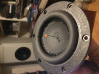
The cone is made from PP, forming an inverted dome with a double injected suspension of santopren. At the center there is a centering hole for the injection inlet. This seem to be perfect for fastening a 3D printed sensor holder that will reinforce pistonic behaviour.
Spec of driver show there is a fairly strong motor and not to soft suspension. Cone weight is 10 g and cone area 27 cm2. Thus not very much SPL. A closed 0.4 litre box with two drivers gives a Qts 0.94
The question is if its a good driver for MFB and second is there a sensor that will fit and weigh only 2g or less?
Attachments

Thanks for your input and I have also studied your MFB thread that contains a lot of good knowledge.Cool! Some observations/suggestions that come to mind based on my limited experience:
- small enclosures with higher system Q's are entirely possible and can even be beneficial in some ways (e.g. for larger drivers, shifting amplitude up at higher frequencies to provide a higher feedback factor at harmonics requiring suppression)
- need to evaluate where/how an accelerometer can be mounted (and what accelerometer and what accel I/F circuitry...)
- watch out for high system Q at new resonance due to increase in effective mass (m+m')
- with reasonably matched drivers an accelerometer in only one should work reasonably well, but you will have to closely match including the added mass on the second driver
- the accelerometer mount needs to be extremely rigid and resonance free in band
- the F3 goal needs to be reasonable for the size of driver. It is unfortunate that drivers have excursion limits. 🙂

Motional Feedback Audio.
Star bass Cling on maybe?
But also remember surface area is whats moving the air. 🙂
Star bass Cling on maybe?
But also remember surface area is whats moving the air. 🙂
Motional Feedback Audio.
Star bass Cling on maybe?
But also remember surface area is whats moving the air. 🙂
Thanks esl63, cling on looks interesting and just about right in size/weight.
Regarding area I will start low and reach for the higher peaks as I catch up with experience... and breath 😉
- Home
- Loudspeakers
- Subwoofers
- Motional Feedback Speaker Project - Circa 1981