Here is some information on an MFB speaker I worked on and eventually made a couple of samples of for my own use back in the early 80s. At some point I hope to analyze it a bit with newer tools and share that information. Hopefully it will be of interest to at least a few. Frankly, I don't think that this will provide any new information for those here who are technically inclined and have experimented with the technology. There are certainly people here with a much better handle on electronics and control theory than I have. But it provides another example of an acceleration feedback system to read about. ")
I haven't worked on this sort of thing since that time but I find myself interested in giving it another go. But I have a lot to learn about the tools being used today for this sort of development. I may need some guidance on that.
But anyways, first a bit of history. Back around 1979, I had what I thought was the brand new, never-before tried and supremely brilliant idea of fixing the non-linearities of a low frequency loudspeaker with some sort of negative feedback. I constructed a very simple op amp adder feedback circuit (pushing the limit of my technical knowledge to the extreme) and fed back a position signal derived from a lamp, LDR and light blocking card attached to the back of the speaker cone to the preamp signal. Well, it worked right away and was stable. What's so hard about this! For a moment, I thought I had solved all the world's problems with accurate low frequency reproduction.
Then reality set in.
I knew it was working because I could push hard on the cone with my fingers and the amplifier was pushing back. If I pushed hard enough, the over-current protection on the amplifier would trip. But I soon discovered it only worked at very low frequencies. And as I rationalized later, it probably was only stable due to an extremely limited bandwidth of the sensor.
So after some trips to the University library, I realized there were already successful implementations of motion feedback using both velocity-sensing coil and accelerometer feedback methods. I discovered the 1968 Philips paper by Klaassen and Koning and discovered an MFB speaker had already been produced in Canada by PSB Speakers. This was the Beta II which employed a Philips MFB driver and, if memory serves, it had been in production since the mid 70's. In pursuit of a B.Eng.Sc. degree I needed a 4th year project so this became the "Motional Feedback Speaker" where I would try to develop a version on my own. Fortunately, I had access to lab equipment and a very good lab technician who frankly ran rings around me on the electronics side of things. And Paul Barton graciously forwarded additional technical articles that were not in the library. Without these, I seriously doubt a good result would have been possible.
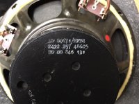
I don't have any pictures of the original prototype, but attached is a pic taken recently of one of the two speakers that were built for my own use back in 1982 along with the MFB control box for a stereo pair. Note the drivers are P/N AD80671/MFB which were round versions of the original octagonal driver P/N AD8067/MFB. I think these were available in the later years the MFB drivers were produced. You could just order these drivers and 12" versions directly from a Philips distributor at the time.
I haven't worked on this sort of thing since that time but I find myself interested in giving it another go. But I have a lot to learn about the tools being used today for this sort of development. I may need some guidance on that.
But anyways, first a bit of history. Back around 1979, I had what I thought was the brand new, never-before tried and supremely brilliant idea of fixing the non-linearities of a low frequency loudspeaker with some sort of negative feedback. I constructed a very simple op amp adder feedback circuit (pushing the limit of my technical knowledge to the extreme) and fed back a position signal derived from a lamp, LDR and light blocking card attached to the back of the speaker cone to the preamp signal. Well, it worked right away and was stable. What's so hard about this! For a moment, I thought I had solved all the world's problems with accurate low frequency reproduction.
Then reality set in.
I knew it was working because I could push hard on the cone with my fingers and the amplifier was pushing back. If I pushed hard enough, the over-current protection on the amplifier would trip. But I soon discovered it only worked at very low frequencies. And as I rationalized later, it probably was only stable due to an extremely limited bandwidth of the sensor.
So after some trips to the University library, I realized there were already successful implementations of motion feedback using both velocity-sensing coil and accelerometer feedback methods. I discovered the 1968 Philips paper by Klaassen and Koning and discovered an MFB speaker had already been produced in Canada by PSB Speakers. This was the Beta II which employed a Philips MFB driver and, if memory serves, it had been in production since the mid 70's. In pursuit of a B.Eng.Sc. degree I needed a 4th year project so this became the "Motional Feedback Speaker" where I would try to develop a version on my own. Fortunately, I had access to lab equipment and a very good lab technician who frankly ran rings around me on the electronics side of things. And Paul Barton graciously forwarded additional technical articles that were not in the library. Without these, I seriously doubt a good result would have been possible.
I don't have any pictures of the original prototype, but attached is a pic taken recently of one of the two speakers that were built for my own use back in 1982 along with the MFB control box for a stereo pair. Note the drivers are P/N AD80671/MFB which were round versions of the original octagonal driver P/N AD8067/MFB. I think these were available in the later years the MFB drivers were produced. You could just order these drivers and 12" versions directly from a Philips distributor at the time.
Attachments
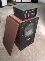
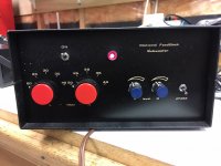
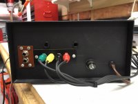
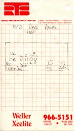
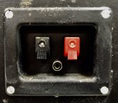
I dug out the MFB control box and took pictures of the front and rear panels. Note the unlabeled connectors at the rear! Fortunately, I found a note in the file that defines the connections so I won't have to take it apart to figure that out. IN is from a preamp, OUT goes to a power amplifier and ACC OUTPUT (IN) is the signal from the accelerometers. The two holes provide access to multi-turn pots to adjust feedback gain.
Attachments
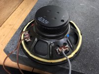
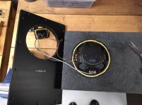
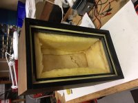
I took some pictures of one of the speakers and took it apart to get a look at the driver. I'll also measure the T/S parameters while I have it apart. I was surprised at the contamination on the exterior surfaces. I guess this sort of thing happens when something sits in the basement for a long time.
Note the extra connection for the accelerometer on the speaker connection plate. I don't know where I found this plate but it was exactly what I needed. Note also the fuse in the front baffle. I usually used a 1.5A Fast Blo to be extra safe but up to 2A was okay. With the fuse I didn't have to worry about damaging the driver if I adjusted the feedback too high or turned the volume up too loud for a particularly "bassy" recording.
Note the extra connection for the accelerometer on the speaker connection plate. I don't know where I found this plate but it was exactly what I needed. Note also the fuse in the front baffle. I usually used a 1.5A Fast Blo to be extra safe but up to 2A was okay. With the fuse I didn't have to worry about damaging the driver if I adjusted the feedback too high or turned the volume up too loud for a particularly "bassy" recording.
Attachments
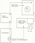
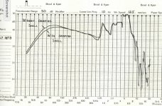
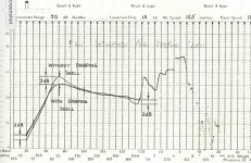
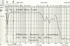
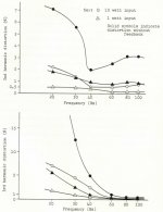
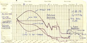
Here is the original test setup to measure the output of the accelerometer and the amplitude response curve. This is a bit of a sidebar, but at the time I was also experimenting with the effect of additional mechanical damping. The difference was more obvious when using a tube amplifier with low damping factor as shown in the last chart.
Attachments
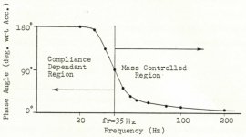
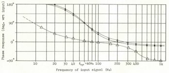
This is a generic graphic from the report I should have included earlier just to illustrate the phase shift that occurs relative to acceleration as a speaker mounted in a closed box goes through its "corner frequency".
Attachments
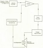
Skipping to other observations and results, here is a block diagram of the system tested, the closed loop amplitude response and the open and closed phase response as documented in the report.
Attachments
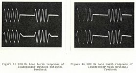
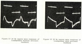
Tone Burst and Transient response as documented in the report. Note the overall system Q without feedback was above one - more on this later.
Attachments
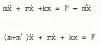
The equation of motion that equates acceleration, velocity and displacement forcing factors to total force provides some interesting results as feedback is applied. Put simply and as originally documented in the Philips paper of 1968, adding different types of feedback impacts the system in different ways:
- acceleration increases mass and Q,
- velocity increases damping reducing Q, and
- displacement feedback increases stiffness increasing Fr and Q
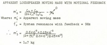
The images show the equation with acceleration feedback. Negative feedback reduces the Force and rearranging indicates the increase in "apparent effective mass". This increase in "apparent effective mass" was clearly observable by forcing the driver with the fingers. It really did feel very heavy.
- acceleration increases mass and Q,
- velocity increases damping reducing Q, and
- displacement feedback increases stiffness increasing Fr and Q
The images show the equation with acceleration feedback. Negative feedback reduces the Force and rearranging indicates the increase in "apparent effective mass". This increase in "apparent effective mass" was clearly observable by forcing the driver with the fingers. It really did feel very heavy.
Attachments
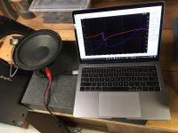
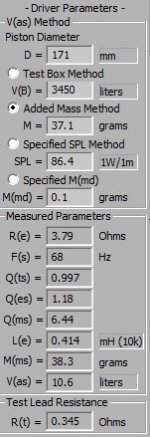
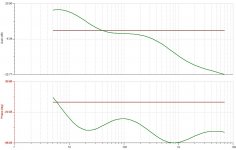
The spec sheets available for the AD8067/MFB driver didn't have T/S parameters back in those days. I tested one of the AD80671/MFB drivers and got the results in the first image from a "DATS V2" measurement tool.
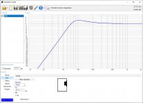
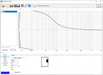
Putting these parameters into WinISD with a 25 litre enclosure and it yielded the transfer function in the next two images. Note the overall Q is almost 1.2. Go back to Post #8.
Putting these parameters into WinISD with a 25 litre enclosure and it yielded the transfer function in the next two images. Note the overall Q is almost 1.2. Go back to Post #8.
Attachments
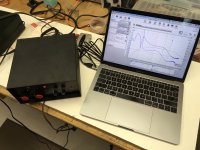
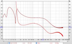
I purchased a USB sound card and figured I could use REW to get a Bode plot of the open loop response of the MFB control box from Line In to Line Out. The first problem was the toggle switch for power was seized and had to be replaced. The second problem was no output. After opening up the box and re-seating all the op amp chips (they are all 8-pin DIPs in sockets) I finally got a signal to measure.
The plot is attached. Note that the path measured includes other circuitry in addition to the Loop Filter within the feedback loop. Namely:
- overall level adjustment (to match the main stereo pair with which these are used), and
- 2nd order high-pass filter (adjustable from 20 - 40 Hz), and
- 10 Hz notch filter (to address system resonance with feedback)
Once these are taken into account, the response seems to look like it should.
Attachments
Hi rascamp.
Interesting - and also quite delightful - that somebody again takes an interest in this. You might be interested in an article I wrote for Speaker Builder some years ago. It is not very sophisticated - and the measuring equipment I had at that time was -to say the least - basic. But the circuit worked. Interestingly, Andrea Ciuffoli (audiodesignguide.com) also took so much interest in it that he scanned the original article and put it on his website (naturally without informing me!). The article kan be read here: http://www.audiodesignguide.com/doc/Acceleration_Feedback_1.jpg - this is the first page, the following pages' Urls are the same apart form ...Feedback_2.jpg etc. (There is also a reference to the original Philips paper + the schematic.)
I also believe I invented af way to use accellerationfeedback in a loudspeaker using just one poweramp. This was also published in Speaker Builder.
Hi rscamp.
Interesting - and also quite delightful - that somebody again takes an interest in this. You might be interested in an article I wrote for Speaker Builder some years ago. It is not very sophisticated - and the measuring equipment I had at that time was -to say the least - basic. But the circuit worked. Interestingly, Andrea Ciuffoli (audiodesignguide.com) also took so much interest in it that he scanned the original article and put it on his website (naturally without informing me!). The article kan be read here: http://www.audiodesignguide.com/doc/Acceleration_Feedback_1.jpg - this is the first page, the following pages' Urls are the same apart form ...Feedback_2.jpg etc. (There is also a reference to the original Philips paper + the schematic.)
Hi Hans.
Your article looks familiar! I think I have a copy of it somewhere. It has been a long time since I last looked at it so I should take another look. Thanks!
Yes, I think motional feedback is an interesting topic and I like how it reduces several types of distortions. You probably know of Chris Camphuisen (Piratelogic). I wonder how well his "EVE" board and "Starbass" accelerometers work?
I also believe I invented af way to use accellerationfeedback in a loudspeaker using just one poweramp. This was also published in Speaker Builder.
Do you have more information on this?
Hi,
Thanks for the link to Chris Camphuisen whom I did not know, but he seems quite dedicated to the idea. As far as I can see from the pictures he also uses piezo discs to measure the acceleration. However, if I were to experiment with it now, I would try a more modern device - for example the ADXL337 or similar.
As for the "one amp" idea - I'll scan the article and (if copyright permits!) post it here some time.
The article from Speaker Builder about a single poweramp accelereationfeedback system:
http://www.hjkm.dk/Audio/Accel_feedback_single_amp.pdf
This is a scan of an ariticle I wrote for a Danish magazine. It is in Danish, of course, but the pictures and schematics may be of interest. (Warning: It is a BIG file!)
http://www.hjkm.dk/Audio/AccelerationsFeedbackSubwoofer.PDF
http://www.hjkm.dk/Audio/Accel_feedback_single_amp.pdf
This is a scan of an ariticle I wrote for a Danish magazine. It is in Danish, of course, but the pictures and schematics may be of interest. (Warning: It is a BIG file!)
http://www.hjkm.dk/Audio/AccelerationsFeedbackSubwoofer.PDF
Hans Jörgen! Your system worked wery well!
I built 10 systems in total based on your article back in the early 90s. This was the reason for me to study electronics. I was a student and the first day with "regulation theory" I went bananas asking too many questions about phase margins and Q-factors.
My 80 or so class mates, who was tired on my questions didn´t really like the subject.
However, me myself loved the lessons and i still keep your magazine in a plastic bag!
rscamp was clever enough to put a fuse in series with the element... i fried several peerless 831857. Fuse is a good thing!
+1...rscamp was clever enough to put a fuse in series with the element... i fried several peerless 831857. Fuse is a good thing!
Ha, ha, I fried a Klipschorn.... one very sad day, 40 years ago.
Not sure a fuse would be fast enough for protection against one real big pulse.
But many of today's muscular sub-woofers can handle more watts than the amps that drive them*. In light of my sad experience, I bought a DVC woofer for experimentation named "Brutus".
B.
* kind of dumb engineering to design drivers that have massively heavy voice coils just to protect crazy audiophiles and MFB experimenters
Last edited:
- Home
- Loudspeakers
- Subwoofers
- Motional Feedback Speaker Project - Circa 1981