rscamp was clever enough to put a fuse in series with the element...
It helps lower the blood pressure when playing with gain. It can also be fun making the fuse glow in the dark with just the right signal. 🙂
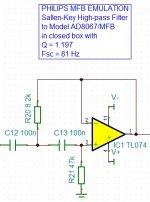
Back in Post #12 we modeled the transfer function for the AD80671/MFB in a 25 litre enclosure. I used an online filter tool to make a circuit that provides a similar response. I'll put this in the feedback path to model the speaker response. I think this would be a valid way to model it with the obvious exception that higher frequency nastiness will be present in the real transfer function for the speaker.
Attachments
Last edited:
This is really getting more challenging for me now! Feel free to point out mistakes in this process or my assumptions.
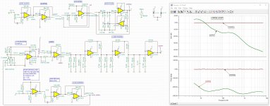
Here is the complete circuit modeled in TINA along with the Open Loop response.
An emulation for the speaker's accelerometer signal is in there but it isn't being used yet.
I bypassed all the "conditioning" circuitry before the feedback portion so an unaltered signal sweep from 5 Hz to 7 kHz is analyzed. The phase of the Loop Filter output confused me at first but I think it has a -180 shift due to the Control Signal going into the inverting input of the ADDER.
Attachments

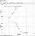
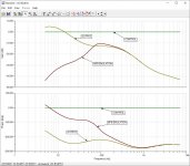
Moving forward with the circuit modeling, here are the combined transfer functions for the CONTROL (Signal In), OUTPUT (Signal Out of the Loop Filter) and MFB EMULATION (Signal Out of the Accelerometer using the modeled response of the closed box speaker). So "MFB EMULATION" represents the predicted Open Loop response of the speaker but as already modified by the Loop Filter.
Attachments
Wow, somebody been busy 🙂 will respond after reading previous posts. Wonderful work done Rob !
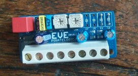
EVE servo evaluation kit
EVE servo evaluation kit
Attachments

Last edited:
Wow, somebody been busy 🙂 will respond after reading previous posts. Wonderful work done Rob !
EVE servo evaluation kit
Hi Chris!
It looks like you got my email. 🙂 I'm looking forward to trying out the EVE board + StarBass accelerometers.
@ chriscam
Hi, i tried to visit your www, but get Nothing at all !
Chris's link was to the EVE board manual:
https://piratelogic.nl/data/docs/products/eve/piratelogic.eve.2018.0.manual.en.pdf
The main site is Motional Feedback Audio. Both work for me.
Will send you the requested info tomorrow 🙂Hi Chris!
It looks like you got my email. 🙂 I'm looking forward to trying out the EVE board + StarBass accelerometers.
Dear esl63
Thank you very much for your post. It's delightful to know that a simpel article actually made a difference - I really had no clue. In the old days of paper-posting feed-back of this kind was a rare thing, whereas nowadays... so thank you.
Hans Jørgen
Thank you very much for your post. It's delightful to know that a simpel article actually made a difference - I really had no clue. In the old days of paper-posting feed-back of this kind was a rare thing, whereas nowadays... so thank you.
Hans Jørgen
I have been playing with MFB around 1979. The Philips drivers where available cheap at that time and the promises where high.
I learned a lot experimenting and today I'm totally convinced the best speaker up to 150Hz is an active cone woofer with some kind of feedback control and DSP room correction.
The question is why this superior principle is not broadly used today.
Amp power has come down to about 100$ for 1000W rms, DSP´s are dead cheap and high quality loudspeakers are available in any size for ridiculous prices, compared to what they where 40 years ago.
For the German DIYS community I can give you an answer. This community is dominated by two publications, the “Hobby HIFI” and the “Klang und Ton”. These publications ignore DIYS active loudspeakers completely. The reason why is quite simple. These publications need a good relation to the commercial sellers of loudspeaker equipment.
Today the cost of the pure chassis is very low. So even selling high end chassis does not create enough profit, the free trade in the EU and resulting competition does not make this situation better for retailers. So a clever producer of coils and capacitors showed the dealership a way out...
Today the components for passive crossovers have skyrocketed to ridiculous high´s.
Very often the price of the loudspeakers is much lower then the necessary crossover kit. Of course, the coils and caps are decorated with wonderful spices. Magazines and dealers tell you great story's about the marvelous sound effects. For example a cap made with gold sounds much better than a regular metal film ore even silver doted one. So , to hear the full potential of your 40$ tweeter, you should at least use a 40$ cap or details get lost. Believe it? Nay, me not.
So, what happens to these expensive parts, if a DSP and 3 chip amps make up the frequency separation?
Right! Mr. Mundorf and his friends will not sell there 1000 times overpriced nonsense parts.
So anything going in this direction, including MFB, is abolished in the DIYS sector. You write about active speaker design? The adds your valued commercial partners regularly buy in your magazine will disappear.
The commercial loudspeaker producers have used MFB in a lot of ways and still use it, as all patents have run out long ago. The problem is, the end user is not interested in such complicated technical details. They mistrust anything “new”.She or he goes to a shop and wants to spend a certain amount of money. The smaller loudspeaker for more money may sound better, the uninformed consumer puts weight and size on the scale and makes her/his decisions where she/he gets more.
So today we find only few active speakers and even less with MFB, usually only in the high end region, where technical interested customers buy.
I think this will change, as DSP and amp chips get cheaper by the hour.
The PA sector does not need MFB, as it does not increase SPL. The limit is still the cone area here. Strong magnets are usually enough to control cone movement and low frequency is not the primary goal, but sound pressure, together with reliability.
Last edited:
@ rascamp
Your idea was used by a small German High End manufacturer about the same time, just a bit refined.
They used a LED, photo transistor and a kind of conical straw that was fixed at the dust cap.
The movement of the straw partially blocked the light from the transistor and they had a reverence of cone movement. As far as I remember, it was only the bass speaker regulated in that way. The electronics was well refined, as it had to find the point of zero cone excursion somehow.
The analog electronics of that time had to be adjusted from time to time, probably the end of many Phillips MFB speakers.
All these developments where somehow blocked, because Backes&Müller had a commercial successful speaker that used different feed back methods and was covered by many patents. Even the B&M tweeter was with feed back, the diaphragm formed a capacitor that reverenced it´s movement.
Beside the award winning B&M reverence speakers, all other MFB speakers where somehow second choice.
MFB could have been the killer application of the 70/80th speaker market, but poor marketing and patent restrictions have blocked it´s break through until today.
With HIFI we are in a funny market, where the final sound of the product is much less important to the majority of customers than it´s image, price and unproven opinions of sales people.
I still think that MFB is the way to go, when you are maxed out with speaker volume.
I have build woofer with feedback from the voice coil, the results where extreme impressing. (small resistor in the minus wire of the woofer to get a signal) I always ask my self how much better “real” sensor based feedback might be and could not find an answer.
After all, to me, it only makes sense to use MFB with large, high excursion woofers. So fitting some sensor is no micro surgical science at all. There are large vents in pole pieces and fat cones of today's sub woofer driver can carry any kind of sensor. So experimenting will not automatically leave ruined woofers behind.
I don´t see any sense in torturing a small woofer to extremes, my goal was always to make a decent woofer better, deeper, more precise.
It is disappointing how few information there is on the web.
Last edited:
Well implemented MFB apart from improving bass response is a phenomenal improvement to overall speaker sound. Better time behaviour and reduced harmonics do clear the midrange quite a bit. Complex piano cords are coming trough like the real thing is in front of you. Not really possible without the MFB (to my knowledge). It will be difficult task to go against the general perception and marketing in the industry but quite a few people are investing time and money in new developments, so hopefully at some stage the MFB will get the following it deserves and we will see more products on the market.
Could the signal be added to its correction mechanically, in a double coil
?
We would get an autonomous unit to be connected to a generic amplifier.
What about a stereo signal? Should we give up?
?
We would get an autonomous unit to be connected to a generic amplifier.
What about a stereo signal? Should we give up?
Interesting perspectives, Turbowatch 2 and exclusive.
Do you mean the unmodified "Control" signal applied to one voice coil and the "Correction" signal applied to the second? Interesting idea, but I would think this would result in a significant efficiency penalty (with the associated added heat) as the forces and associated currents would be working against each other at times.
Not sure what you mean. Can you elaborate?
Could the signal be added to its correction mechanically, in a double coil?
Do you mean the unmodified "Control" signal applied to one voice coil and the "Correction" signal applied to the second? Interesting idea, but I would think this would result in a significant efficiency penalty (with the associated added heat) as the forces and associated currents would be working against each other at times.
We would get an autonomous unit to be connected to a generic amplifier.
What about a stereo signal? Should we give up?
Not sure what you mean. Can you elaborate?
No, you can not generate a signal from a second voice coil and use it directly to modify the signal. It will not have enough energy ever and interfere with the driving amp.
......I have build woofer with feedback from the voice coil, the results where extreme impressing. (small resistor in the minus wire of the woofer to get a signal) I always ask my self how much better “real” sensor based feedback might be and could not find an answer.".......
Would you mind sharing the circuit? I would like to see how much it differed from Mr. Eraths which his patent has long expired.
- Home
- Loudspeakers
- Subwoofers
- Motional Feedback Speaker Project - Circa 1981