Very sophisticated.It never makes sense to use a BR (imho).... You just have to design them to work with a negative output impedance from the beginning.
Unless you use a mic picking up sound as the sensor (which seems impossible to do successfully), you are sensing the motion of the cone. So the question is: how does the cone motion track the sound output.
The BR box, for example, has two "voices", the cone and the port, and also they have a complicated and convoluted phase relationship. So the cone motion isn't a very good guide to the sound output around the resonances. But I suppose you can use MFB for some benefits.
A TL behaves a lot like a BR but the designer has a few more points of control.
With a true horn, the cone motion and sound output are not perfectly matching, but pretty good.
With a sealed box and piston-like cone, very good.
B.
The BR box, for example, has two "voices", the cone and the port
And almost no where else do you see a declining radiating surface area with lower frequency.
A 15 inch driver with a 4 inch port is analogous to a 15 inch midbass driver with an extreme long xmax 4 inch bass driver which takes several cycles to reach peak displacement after the midbass driver.
A normal bass reflex Helmholtz resonator takes several cycles to reach full amplitude - long after the true peak of the transient signal (drums etc). During this time of resonant build up of the port and the air volume the driver is less loaded by the Helmholtz resonator then at a steady state sine wave.
It is no wonder BR lack punch and attack compared to horns or high order quarter wave alignments.
A TL behaves a lot like a BR but the designer has a few more points of control
This is only true for steady state signals. They behave very differently at transient and dynamic signals (music).
PCF lowers distortion substantially and increases the control of the driver (especially below tuning) for horns and high order QW. A most welcome feature in every way. It is very easy to hear the sudden increase in control, the greatly increased definition and the vigorous dynamic precision when applying PCF while driving a large back loaded horn or ODQW.
My small rats nest Class A amp with PCF made my small and cheap 6,5 inch Car audio Coax sound like a large heavy duty 12 inch dedicated subwooofer right up to it started exceeding xmax and the distortion skyrocketed.
When it powered my large BIB back loaded horn with a B&C 10PS26 it produced some of the best bass I have heard (within the 2 watt limits of course).
The same amp without PCF (an alligator clip shorting R-Sense) did manage to sound nice but somewhat laid back with a little lack of control and definition.
The difference was startling and very demonstrative of the benefits of PCF.
https://rmsacoustics.nl/papers/whitepaperMFBdesign.pdf
This paper clearly confirms the benefits of PCF ( current feedback)
Specially together with MFB.
This paper clearly confirms the benefits of PCF ( current feedback)
Specially together with MFB.

https://www.powersoft-audio.com/cn/downloads/white-papers/922-powersoft-bac-ipalmod-system-introduction/file
Powersoft and B&C has a whitepaper on similar technology and they reference Ace-bass.
Right... Powersoft and B&C has a whitepaper on similar technology and they reference Ace-bass.
Just a battle to be able to claim patenting rights based on trivial changes.
I guess recent posters agree some feedback does so much good, it doesn't matter if it is the best method or the next-best method.
B.
Hello, indeed seems to be very interesting topic this MFB and lots of reading has popped up recently. Have you guys seen the Kokorianz circuits from solid state forum? started from this sublimed JLH1969 and a new design here NEW class A :Constant Current Push Pull amplifier with single SMPS and hybrid preamp
I don't understand much of it, but seems to be somekind of feedback through the speaker load. I've read the threads many times and hoped there was more discussion but not much action there... What do you think? seems to be simple build (sublimed jlh), I have to try it someday. I've never had a class A poweramp nor MFB system 🙂
I don't understand much of it, but seems to be somekind of feedback through the speaker load. I've read the threads many times and hoped there was more discussion but not much action there... What do you think? seems to be simple build (sublimed jlh), I have to try it someday. I've never had a class A poweramp nor MFB system 🙂
Last edited:
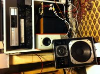
A couple of month ago I bought a pair Philips MFB 586 from the late music directors estate. I paid 35 USD including the complete Black Tulip package in its original boxes. All in mint condition from one owner only.
Initial tests of all equipment indicated bad connections in general. Changing all e-caps with guidance from MFB forum in Holland among others, I got them all to work fine, except for the MFB.
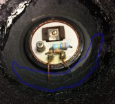
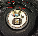
When calibrating the MFB I found the connection was broken to voice coil and MFB sensor. By resistor measuring and with help of a needle I could locate the ruptured connections to be in the vicinity of the glued joint of cone and voice coil.
The reason for the broken connections is indicated on the photo. I suspect the added sensor mass and higher acceleration by MFB increase the force above the maximum designed strength of the cone assembly. It may be a sudden breakage or fatigue stress in material.
With jeweler glasses on, bright light and a brain surgeons steady hands I managed to solder new tinsels in place and repair the rupture with 2-components resin.
After recalibration amps V p-p output and feed back according to service manual I could hear the obvious clarity and deeper bass compared to no MFB. Inspired by this work I started to look for more MFB experience and found this thread being very interesting and full of knowledge.
So now I wonder, how do I further improve or optimize the MFB of my Philips, e.g. is it by meassuring the acoustic output and adjust until some curves adaption or else?
Initial tests of all equipment indicated bad connections in general. Changing all e-caps with guidance from MFB forum in Holland among others, I got them all to work fine, except for the MFB.
When calibrating the MFB I found the connection was broken to voice coil and MFB sensor. By resistor measuring and with help of a needle I could locate the ruptured connections to be in the vicinity of the glued joint of cone and voice coil.
The reason for the broken connections is indicated on the photo. I suspect the added sensor mass and higher acceleration by MFB increase the force above the maximum designed strength of the cone assembly. It may be a sudden breakage or fatigue stress in material.
With jeweler glasses on, bright light and a brain surgeons steady hands I managed to solder new tinsels in place and repair the rupture with 2-components resin.
After recalibration amps V p-p output and feed back according to service manual I could hear the obvious clarity and deeper bass compared to no MFB. Inspired by this work I started to look for more MFB experience and found this thread being very interesting and full of knowledge.
So now I wonder, how do I further improve or optimize the MFB of my Philips, e.g. is it by meassuring the acoustic output and adjust until some curves adaption or else?
Attachments
Congratulations and good repairs.
Always a puzzle how to evaluate MFB systems. Big problem with the Philips gear because they started with a medium quality speaker and added medium quality MFB parts. But the results, I am told, are exceedingly good bass despite the small size.
MFB adds very impressive "fast", impactful, low, and clean bass sound. So you can judge that by ear compared to otherwise similar boxes. Likewise, measurement should look good, again relative to what you might expect.
I don't know enough about the unit to offer any advice. With too much feedback - audio or anything else - you run into howl-back positive boost. Assuming your Philips amps aren't strong enough to cook the woofer, you are prolly safe in exploring how much feedback you can live with as the weather changes and so on: but take care.
Nice if you can keep us informed, even just your trials and errors.
B.
The reason for the broken connections is indicated on the photo. I suspect the added sensor mass and higher acceleration by MFB increase the force above the maximum designed strength of the cone assembly. It may be a sudden breakage or fatigue stress in material.
It's the latter, especially with modern bass rich music the woofers cone excursion easily stretches available tinsel length. Remember these drivers were designed late 70ties, early eigthies with mainly analog sources in mind.
Yes, the factory procedure is kinda raw using average values, better is to feed it pink noise and adjust for maximum fr flatness as shown in my video below where I adjust the feedback loop with one of my Little/One MFB systems.So now I wonder, how do I further improve or optimize the MFB of my Philips, e.g. is it by meassuring the acoustic output and adjust until some curves adaption or else?
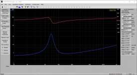
Thanks Bentoronto and Chriscam for your comments and advice. And yes, the service manual was obviously only to get the setting within a rough frame. Attached diagram show the close field SPL at the aperture of the bass in max and min setting.
The benefit is obviously both deeper bass and flatter respons at the same time as the THD is remarkably lower. On top of all the speaker pair measures are almost identical. The stage image of the speaker pair stays wonderfully solid.
There is a -5dB notch however at 1.1kHz with a negative influence in the XO area. As the pair are identical in regards to the notch I suspect this is from the feed back. Any ideas about whats causing it?
Attachments

Anyone who sees the plot will immediately claim they detect the 1000 Hz flaw. But anyone not seeing the plot first will never hear it or its absence.
Can you please post what each of those curves is.
B.
Can you please post what each of those curves is.
B.
Sorry, I got carried away in the middle of night here. The set up of SPL test was made with a calibrated mic flush with center of cone aperture. The red SPL and grey THD curve is with MFB set to min. Green SPL and yellow THD curve with MFB set to max.
The dip at 1.1kHz is actually -15dB. The distance from mic to tweeter center was 165mm. This is about a half wavelength at 1.1kHz. The tweeter was connected and might contribute to cancelling? I will check.
I will measure Fr with MFB disconnected and the MFB signal isolated. I will post the result when done.
Those plots are about the best advertisement for MFB I can imagine. The FR looks wonderful and the THD improvement is excellent and couldn't be accomplished any other way. Didn't realize the speaker's MFB worked so well. Of course, the more relevant result is measured at your chair.
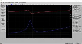
One interesting plot is the MFB electric signal sent back to the amp when the system is intact. What is the MFB telling the amp?
A chance at 1kHz you are picking up cancellation (just like the folks who erroneously play L and R speakers simultaneously and the treble has mysterious dips). Measuring at a distance might be revealing.
B.
The stabilization effect of added mechanical damping in the frequency response plots of Post #5 strongly suggests the 1.1kHz aberration is related to a modal in the driver structure.
Thanks for your comment Rscamp. I belive you are right.
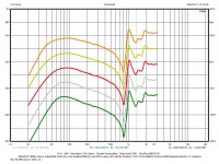
Test of AD81671/MFB in free air and well clamped. TS parameters by added mass 20g.
Curves from sensor output at no load. Dc supply 5.4V. Starting from bottom P 0.05W, 0.2W, 0.8W, 3.2W and 13W.
Test of AD81671/MFB in free air and well clamped. TS parameters by added mass 20g.
Curves from sensor output at no load. Dc supply 5.4V. Starting from bottom P 0.05W, 0.2W, 0.8W, 3.2W and 13W.
Attachments
Thanks for your comment Rscamp. I belive you are right.
Test of AD81671/MFB in free air and well clamped. TS parameters by added mass 20g.
Curves from sensor output at no load. Dc supply 5.4V. Starting from bottom P 0.05W, 0.2W, 0.8W, 3.2W and 13W.
To further confirm a mechanical resonance, look for abrupt phase shifts around 1.1kHz.
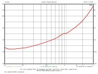
Measured T/S parameters for the Philips drivers purchased in 1982(?) currently in the refurbished system are attached for reference.
Attachments
Last edited:
Thanks for feedback plots. The feedback (for example, red trace) nicely captures the raw speaker output (red trace in earlier plot), allowing for some oddities north of 1kHz where the system seems to struggle to remain on track.
The maximum electric feedback seems to be about 15dB: the acoustic output boost at 30 Hz looks about 15dB. The reduction in THD at 30 seems about 15dB. Seems pretty good to me.
No wonder there are many who were/are impressed with this modest speaker.
And now for the real test: can you record something played with and without the MFB connected?
A small chance my cowbell might be revealing.
B.
Attachments
rscamp
To further confirm a mechanical resonance, look for abrupt phase shifts around 1.1kHz.
I looked at my drivers impedance curve which indicate the origin of the 1.1kHz notch. According to the litterature the stiff cone break up should be at 896 Hz. Above the Ft, transition frequency, the cone is not working as a piston any longer.
The increased acceleration at this point is fed back by the sensor. Looking at the SPL output the notch is independent of MFB set min or max. Assume this is correct, is it practical/possible to add a steeper LP filter to get rid of it?
rscamp
Measured T/S parameters for the Philips drivers purchased in 1982(?) currently in the refurbished system are attached for reference.
The TS parameters of your drivers are very much the same as the ones I have. Despite old drivers considered being "cheap" I am impressed by the small variations of the parameters.
Attachments
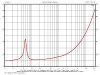

I looked at my drivers impedance curve which indicate the origin of the 1.1kHz notch. According to the litterature the stiff cone break up should be at 896 Hz. Above the Ft, transition frequency, the cone is not working as a piston any longer...
Can you look at the accel output? This would be affected by the first modal cone breakup but would also reveal resonances in other structure such as the accel mounting etc. Or maybe you have already observed this...
The increased acceleration at this point is fed back by the sensor. Looking at the SPL output the notch is independent of MFB set min or max.
So there is little or no feedback at this frequency. Good thing, as it would be perilous!
Assume this is correct, is it practical/possible to add a steeper LP filter to get rid of it?
Sure - but outside of the feedback loop. But if the corner for the LP response no longer meets the corner for the HF driver HP filter it will create a dip.
- Home
- Loudspeakers
- Subwoofers
- Motional Feedback Speaker Project - Circa 1981