Still waiting for the new stripper accelerometer pcbs to arrive 🙂Chris I'm stuck in the house ( as many others around the globe..) and have a hot soldering tool melting for action 😀

Hi Chris!
Would it be beneficial to place 8 accellerometers on the board. 4+4 series and parallell, where 4 of them is mounted up side down giving invers signal, (i guess you are already doing that) giving 4*voltage out and half impedance?
Would it be beneficial to place 8 accellerometers on the board. 4+4 series and parallell, where 4 of them is mounted up side down giving invers signal, (i guess you are already doing that) giving 4*voltage out and half impedance?
Hi Chris!
Would it be beneficial to place 8 accellerometers on the board. 4+4 series and parallell, where 4 of them is mounted up side down giving invers signal, (i guess you are already doing that) giving 4*voltage out and half impedance?
In order to produce a similar SPL large driver can do with less excursion then smaller ones resulting in a lower accelerometer output, to compensate for sensor signal loss you may choose to put them in series. The downside is that sensor capacitance wil also decrease (1/Ctotal = 1/C1 + 1/C2 + 1/Cx) upping the sensors lower F3 resulting in Lf instabilities requiring fuses 🙄 To compensate for the lower C you might increase the value of R2 - like Philips actually did with their second MFB series, the original R2 was 10M, the 586 LejonKungen dissected has 33M - but that will negatively affect the loop S/N ratios. The best solution for increasing sensor output is like esl63 described: putting sensor elements in series/parallel like done with early StarBass 54 versions: for 2P operation upto 8 inch (2 elements A,B) sufficed, for larger cone diameters 2S2P (extra pair - C,D) - was used:

Chris I'm stuck in the house ( as many others around the globe..) and have a hot soldering tool melting for action 😀
Since delivery of my new Stripper proto suffers from Corona delays and you seem anxious to get started I dug up some old Little/One accelerometers to get you started started:

This is what they look like assembled:

Total pcb weight for two sensors including connection strips, I assume a 19mm mod will weigh between 1 and 2 gramms :

Their diameter is 26mm so you need to Dremel some FR4 material away:

Due to an error in the used PNP shape 😱 it needs to be omitted when building the sensor, here is the component layout:

I'll be in contact via whatsapp for shipping details.
Last edited:
there are current sensors that are based on the Hall effect or those that use the magnetoresistive effect (MR) one of these materials is permalloy.
both are based on the same principle but use it differently, each conductor carrying current creates a magnetic field proportional to the amount of current flowing through.
these sensors exploit this principle and produce a voltage at their output which is proportional to the current.
they can have a through current resistance of 0.0001ohm.
I leave the floor to those who know more than me.

resistors are not without problems.
noise and thermal drift.
if I listen to the loudspeakers at high volume, a lot of current flows and these problems are accentuated. however it remains the simplest way to implement MFB but then you have to add the rest of the electronics. Do you have any wiring diagrams to show?
noise and thermal drift.
if I listen to the loudspeakers at high volume, a lot of current flows and these problems are accentuated. however it remains the simplest way to implement MFB but then you have to add the rest of the electronics. Do you have any wiring diagrams to show?
That's a really complex and sophisticated bit of machinery for substituting for a resistor.
But tell us, arivel, how a complex bit of machinery with a 1.5% error (or more, depending on how you trust manufacturers' specs, how "slippery" is the definition of "Full Scale", and the power you are supplying to it) can be useful for reducing distortion adequately, other than controlling major speakers resonance(s)?
I don't want to be mistaken for a grouchy believer in the old ways of doing things. Accelerometers and other new-fangled methods like this integrated device are great tools and I've tried 'em.
B.
Attachments
this is an example of the other technology
https://datasheet.ciiva.com/25627/0900766b81112064-25627593.pdf
https://datasheet.ciiva.com/25627/0900766b81112064-25627593.pdf
I am confused. When using this kind of device, are you trying to sense the electric signal to the driver or are you trying to sense an electric signal from a motion sensor or somehow sense the motion directly with this device?
B.
B.
Current feedback in the inner loop gives not only lower high order distortion, but also it gives higher phase margin!
This is good since we can crank up the motional feedback with some extra dBs!
And this gives significant reduction in the end.
I have reached -22dB with PirateLogics PCB from chriscam.
I will write more about this in another thread.
This is good since we can crank up the motional feedback with some extra dBs!
And this gives significant reduction in the end.
I have reached -22dB with PirateLogics PCB from chriscam.
I will write more about this in another thread.
These are tactical issues. But in terms of design strategy, when you are working with back-EMF, you are working entirely within the same electric sphere. But when you take guidance from an accelerometer, you are taking negative feedback from an external source and mixing it into the speaker drive. (Which is the very obvious reason you can't use a microphone, as always first comes to mind for feedback, eh.)
As anybody who has worked with motional feedback can tell you, dealing with feedback phase with speakers can be very very tricky and lead to catastrophes when the weather changes or whatever.
B.
As anybody who has worked with motional feedback can tell you, dealing with feedback phase with speakers can be very very tricky and lead to catastrophes when the weather changes or whatever.
B.
Well you have to make sure you are within 45deg of phase margin, then you will be ok. I have tried to crank it up close to 0 deg, then the bass cone is sounding "metallic" when you knock on it. Quite fun to look on a power meter of your amplifier when you knock on the cone AND the signal input is Zero (silent). The amplifier sends out a huge power peak to adjust (back) the cone to Zero position and you hear that metallic ringing. Now you know you are really too close to the fire. Better adjust down the feedback and play safe... Even with 45deg phase margin you can do the knock test, the metallic sound is gone but the power meter will still go crazy!These are tactical issues. But in terms of design strategy, when you are working with back-EMF, you are working entirely within the same electric sphere. But when you take guidance from an accelerometer, you are taking negative feedback from an external source and mixing it into the speaker drive. (Which is the very obvious reason you can't use a microphone, as always first comes to mind for feedback, eh.)
As anybody who has worked with motional feedback can tell you, dealing with feedback phase with speakers can be very very tricky and lead to catastrophes when the weather changes or whatever.
B.
Yes indeed. Well said.
The otherworldly experience of pushing on the cone and having it feel like a solid wall is a very gratifying moment when you move into MFB.
B.
The otherworldly experience of pushing on the cone and having it feel like a solid wall is a very gratifying moment when you move into MFB.
B.
Do you have schematics and electrical circuits to show you ?Wheatstone Bridge, current feedback, are excellent sensors and greatly simplify the system compared to accelerometers, home-brew or purchased. I can't recall seeing the methods tested for comparison.
Here's a little gem from 1958. Explains a lot. Wheatstone Bridge method.
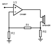
But current feedback is inconceivably simple: just put a small resistor (say, .5 Ohm) in series with the woofer (between the woofer and ground) and tap the feedback off the top end of the resistor. Then you make a little mixer to add the feedback into the amp input, plus some EQ.
And I always add this suggestion, make sure during R&D that your woofer can handle more power than your amp can supply.
Attachments
Last edited:
- Home
- Loudspeakers
- Subwoofers
- Motional Feedback Speaker Project - Circa 1981