Partial notch
May I propose the attached circuit as a possible solution to pre-filter under discussion.
It's a simple inverting BPF, summed with the unfiltered output from the unit under test. As a first cut, I've assumed a 1kHz test, and filter Q of 5. Gain to distortion and noise is R7/R6, 20dB in the schematic, but can be increased with larger R7. R9 allows adjustment to any suitable null depth. R2 can be tweaked to allow center frequency adjusted a few percent. Topology is non-inverting so common-mode distortion mechanisms are avoided.
I hope this posts correctly. I'm very much a newbie and feel very clumsy with the edit tools.
Best.
View attachment Analyzer pre-filter.pdf
View attachment Pre-filter math.pdf
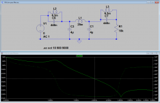
1 KHz passive low pass filter
I made a crude effort to duplicate the CLT filter at 1 KHz. Of course real inductors and caps are not going to work exactly as the models predict and these inductors will be pretty large but this is a starting point. Its much cut, fit, and see as opposed to a careful circuit synthesis. It seems the performance is pretty consistent as the load changes from 100 Ohms to 10 K Ohms. In the simulation it's about -40 dB at 2 KHz and -70 dB at 3 KHz.
I made a crude effort to duplicate the CLT filter at 1 KHz. Of course real inductors and caps are not going to work exactly as the models predict and these inductors will be pretty large but this is a starting point. Its much cut, fit, and see as opposed to a careful circuit synthesis. It seems the performance is pretty consistent as the load changes from 100 Ohms to 10 K Ohms. In the simulation it's about -40 dB at 2 KHz and -70 dB at 3 KHz.
Attachments
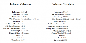
Here are inductor designs for the 1 KHz filter. They are quite substantial and this is not really ideal even. The 3/4 Lb of copper says this is an undertaking. They should be segmented or the parasitic capacitance will degrade the performance. I would also use Litz wire to get the best performance on the higher frequency attenuation. Maybe 24 AWG is larger than needed. I would defer to a local magnetics expert (please) for a better implementation.
Attachments
BSST- The PDF's attached fine.
That is the alternative to the VCVS I had seen somewhere. It should work well as long as the impedances are optimized for noise without overloading a previous stage. It would be a lot smaller than the LC filter I just posted. However, it's still limited by the intrinsic distortion of the opamps.
That is the alternative to the VCVS I had seen somewhere. It should work well as long as the impedances are optimized for noise without overloading a previous stage. It would be a lot smaller than the LC filter I just posted. However, it's still limited by the intrinsic distortion of the opamps.
Doug Self has a new book on filters. I ordered it last week. Appears comprehensive.
His work is always interesting, well written and full of actual measured performance.
-THx-RNMarsh
His work is always interesting, well written and full of actual measured performance.
-THx-RNMarsh
I tried this but there is pole canceling effect even with active component buffering.
show me the schematic/topology you used. pls.
-RM
It's posted somewhere in this thread. Give me a few days. I think I might be able to find something to fulfill you quest.
Last edited:
An osc/gen with potential is on eBay. Selectable freqs and low thd for 30 dollars. Postage paid. Says <01%. Could be .005% or ? Uses 5534 types but in sockets. Might be cheap easy low distortion with some opamp changes and tweaks.

Low distortion(0.01%) sine wave generator (oscillator) module with CD test disc | eBay
-RNM
Low distortion(0.01%) sine wave generator (oscillator) module with CD test disc | eBay
-RNM
Last edited:
Richard:
Next time please include the link Low distortion(0.01%) sine wave generator (oscillator) module with CD test disc | eBay
its interesting. Not sure how tweakable it is.
There is also this:
Assembled Low Distortion Audio Range Oscillator 1KHz Sine Wave Signal Generators | eBay $14. I have one but did not get into tweaking it. Given the lengths Victor goes to to get performance this may only make sense as a bare board effort: Low Distortion Audio Range Oscillator 1KHz Sine Wave Signal Generator PCB Board | eBay and then you select and tue every key component.
Richard:
Next time please include the link Low distortion(0.01%) sine wave generator (oscillator) module with CD test disc | eBay
its interesting. Not sure how tweakable it is.
?? I did. It's below the picture.
I ordered one so you don't have to. .... so i can play around with it and pass on info to others. I'm also going to apply post LP filtering to it using IC filter.
Nice thing about it is -- it is Not one freq only per pcb.
Distortion goal is modest -115 -120dbv (or better). Which is suitable for many DIY projects.
THx-RNMarsh
Last edited:
(snip) Given the lengths Victor goes to to get performance this may only make sense as a bare board effort: Low Distortion Audio Range Oscillator 1KHz Sine Wave Signal Generator PCB Board | eBay and then you select and t[r]ue every key component.
Oh wow, and for all of that we get less that .1percent. Hmmm, I was going to toss the little oscillator that I had because it was only .05percent. Then RichEEM informed me that it was pretty good and to not throw it away. I didn't and it works just fine for a variety of things. It a leader 1302s or something like that it does the regular stuff from Tri, square, percent, etc. from .2 Hz to 2MHz or there abouts. I think we want the oscillators that actually oscillate a sine wave and not the triangle oscillators that are made into a psuedo-sinewave. Yes?
Cheers,
I used a function generator with 16 bit oscillator. Then ran it thru a miniDSP filter.

With no LP filtering

1KHz LP filtered

I checked with an ULD source and the residual is all from the miniDSP. Maybe better parts/opamp is needed. But shows the idea of adding a LP filter to an inexpensive osc output will produce potentially very low THD.... good enough for sound-card style analyzer use. It works very well. A passive filter could be used also. But not as flexible.
I'll find a cleaner DSP filter and try again. Or maybe try replacing parts in miniDSP. I like being able to dial in any LP filter freq with the miniDSP.
THx-RNMarsh
With no LP filtering
1KHz LP filtered
I checked with an ULD source and the residual is all from the miniDSP. Maybe better parts/opamp is needed. But shows the idea of adding a LP filter to an inexpensive osc output will produce potentially very low THD.... good enough for sound-card style analyzer use. It works very well. A passive filter could be used also. But not as flexible.
I'll find a cleaner DSP filter and try again. Or maybe try replacing parts in miniDSP. I like being able to dial in any LP filter freq with the miniDSP.
THx-RNMarsh
Last edited:
If you are filtering in dsp the ad and da are the limitations. You can start with a perfect sinewave digital file and go to a really good dac and get low distortion. It would be limited by the dac. Digital filtering would not help in that case.
Analog filtering of the dac is a different story. SRS does that in their low distortion source with an array of filters to switch in.
Analog filtering of the dac is a different story. SRS does that in their low distortion source with an array of filters to switch in.
the opamps used in the miniDSP are limiting it, also. The opamp ___2068 which is spec'ed for typical thd of -100 (,001%). But -110dbv shown is usable for a lot of products as it is.
I have ordered OPA1612 to replace I/O opamps. If that is all it needs, then we have a nice clean variable filter to use with cheap variable freq generator (Hantek HDG2012B. A nice general purpose Arb. function generator).
THx-RNMarsh
I have ordered OPA1612 to replace I/O opamps. If that is all it needs, then we have a nice clean variable filter to use with cheap variable freq generator (Hantek HDG2012B. A nice general purpose Arb. function generator).
THx-RNMarsh
What is the minidsp using for DAC/ADC? It may be onboard the DSP engine. In any case it will be the distortion limiter more likely. I don't really see value in digitizing a sine wave, filtering it and converting back to analog if you can start with a digital sine wave with less than -180 dB harmonics. There are only a handful of DAC's that can get below -120 harmonics and none are in minidsp stuff I could find.
Its an alternative for less than the best but -110-120db will do fine for many people when using a less costly sine wave frequency generator. Modest distortion generator can be cleaned up with LP filter..... passive or active. Flexibility of using any frequency is a plus.
For those who want the lowest ever thd can use a ULD fixed freq gen and a fixed passive LP filter.
Let's design a 1KHz LP passive filter of high slope. Use it with anyone's gen.
THx-RNMarsh
For those who want the lowest ever thd can use a ULD fixed freq gen and a fixed passive LP filter.
Let's design a 1KHz LP passive filter of high slope. Use it with anyone's gen.
THx-RNMarsh
Last edited:
Why don't you generate the signals on a PC and play it back from your Benchmark DAC3. It will be much lower distortion than using the miniDSP. As Demian mentioned, it's pointless to use an ADC to digitize the test waveform. The miniDSP also uses the built-in DACs of the DSP or a cheap Cirrus converter depending on the model. The JRC2068 is probably not the limiting factor.
Last edited:
Demian missed the whole point of the exercise. I am only using the miniDSP because I have it to try as a LP filter to see how effective a LP filter can be in cleaning up a gen output. And, I can quickly change slope and freq to see affect on gen's thd.
But a passive fixed LP filter would be fine now that I am encouraged with LP filter results.
THx-RNMarsh
But a passive fixed LP filter would be fine now that I am encouraged with LP filter results.
THx-RNMarsh
Last edited:
I have ordered OPA1612 to replace I/O opamps. If that is all it needs, then we have a nice clean variable filter to use with cheap variable freq generator.
THx-RNMarsh
Here is the minDSP variable LP filter with its output opamp changed to OPA1612. and using a better gen. (also variable freq).
2H and 3H are near -120dBv.

THx-RNMarsh
Last edited:
That isn't bad. Oh, but you changed the generator too? What does it look like with the same generator used in your first try before changing the MIniDSP OpAmps with the MiniDSP with the new OpAmps?
Then with the new generator without any LP filtering? What are the different generator?
When we change two things we can't see which change did what. Yes, I know the goal is lower THD and you got there. I'm just curious what just the opAmp change did.
Cheers,
Then with the new generator without any LP filtering? What are the different generator?
When we change two things we can't see which change did what. Yes, I know the goal is lower THD and you got there. I'm just curious what just the opAmp change did.
Cheers,
- Home
- Design & Build
- Equipment & Tools
- Low-distortion Audio-range Oscillator